 |
|||
|
|
|||
|
|
|||
| ||||||||||
|
|
 TM 9-2320-366-20-3
This task covers:
a. Removal
c. Follow-On Maintenance
b. Installation
INITIAL SETUP
Equipment Conditions
Materials/Parts
Engine shut down (TM 9-2320-366-10-1).
Grease, Molybdenum Disulfide (Item 24,
Tools and Special Tools
Tool Kit, Genl Mech (Item 46, Appendix C)
Wrench, Torque, 0-200 lb-in. (Item 59, Appendix C)
Socket Set, Socket Wrench (Item 35, Appendix C)
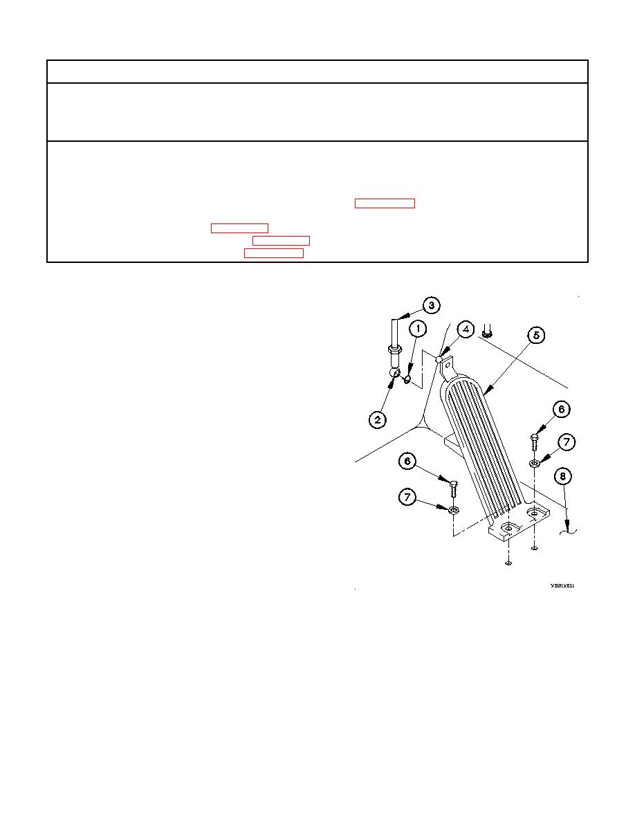
a. Removal.
(1) Remove clip ring (1) from ball seat (2).
(2) Remove ball seat (2) and threaded rod (3) from ball stud
(4).
(3) Remove two screws (6), washers (7), and accelerator
pedal (5) from cab floor (8).
b. Installation.
(1) Position accelerator pedal (5) on cab floor (8) with two
washers (7) and screws (6).
(2) Tighten two screws (6) to 72-84 lb-in. (8-10 Nm).
(3) Apply grease to inside of ball seat (2).
(4) Install ball seat (2) and threaded rod (3) on ball stud (4).
(5) Install clip ring (1) on ball seat (2).
c. Follow-On Maintenance.
(1) Start engine (TM 9-2320-366-10-1).
(2) Depress accelerator pedal and check for smooth
operation.
(3) Shut down engine (TM 9-2320-366-10-1).
End of Task.
4-102
|
|
Privacy Statement - Press Release - Copyright Information. - Contact Us |