 |
|||
|
|
|||
|
|
|||
| ||||||||||
|
|
 TM 9-2320-211-34-2-1
FRAME 2
NOTE
R e a d i n g s must be within limits given in table 8-6. The
letter L shows a loose fit and the letter T shows a tight
f i t . I f readings are not within given limits, throw away
part and get a new one.
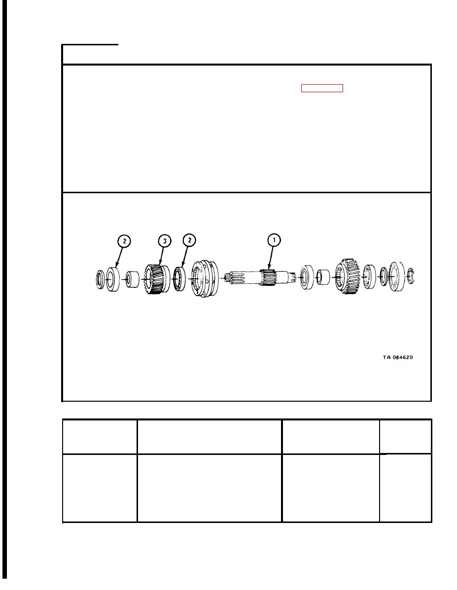
Measure o u t s i d e diameter of input shaft (1).
1.
Measure f i t of bearing (2) on input shaft (1).
2.
Measure i n s i d e diameter of gear bore (3).
3.
Measure f i t of bearing (2) in gear bore (3).
4.
GO TO FRAME 3
NOTE
CHECK ONLY THOSE PARTS WHICH ARE CALLED OUT
PARTS WITHOUT CALLOUTS ARE SHOWN ONLY FOR
REFERENCE PURPOSES.
Input Shaft High Speed Gear Assembly Wear Limits
S i z e and Fit
Wear Limit
of New Parts
Index Number
Item /Point of Measurement
(inches)
(inches)
2.1651
2 . 1 6 5 1 to 2.1656
1
Input shaft outside diameter
0.0003L
0 . 0 0 0 8 T to 0.0003L
1 and 2
Fit of bearing on shaft
0.00007L
0.0009T
to
0.0007L
Fit of bearing in gear
2 and 3
3.9371
3 . 9 3 6 1 to 3.9371
3
Inside diameter of gear
|
|
Privacy Statement - Press Release - Copyright Information. - Contact Us |