 |
|||
|
|
|||
|
Page Title:
Figure 2-1. Radio set simulator chassis assembly, rear view, showing location of parts. |
|
||
| ||||||||||
|
|
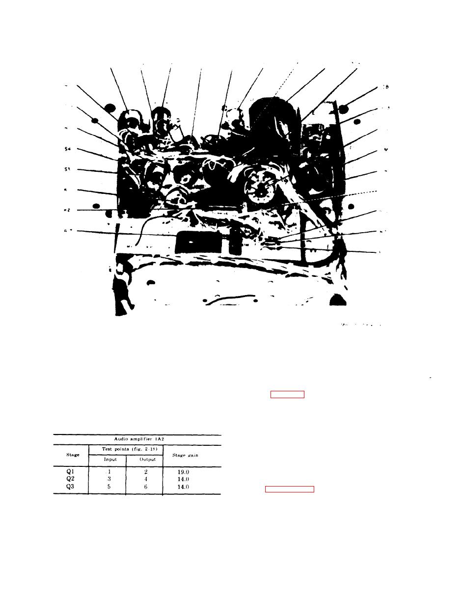 TM 11-6625-564-45
Figure 2-1. Radio set simulator chassis assembly, rear view,
showing location of parts.
(3) If the gains of the stages are abnor-
for 0.1 volt ac at 3 kc. Use the ME-
mally low, use isolating techniques
30B,/U, and measure the voltage be-
(para 2-6) to determine the defec-
tween the test points, listed in the
tive part within the stage.
ground.
chart below, and chassis
Compute the gain in the same manner
as in (1) above.
2-6. Isolating Troubles
When trouble has been localized to a subas-
sembly, use the techniques listed below to
isolate the defective part.
a. Take voltage measurements at the ter-
minals of the subassembly as indicated in ap-
plicable figures 2-13 through 2-16, or 4-13.
26
|
|
Privacy Statement - Press Release - Copyright Information. - Contact Us |
