 |
|||
|
|
|||
|
|
|||
| ||||||||||
|
|
 TM 11-6625-56445
Correction
Symptom
Probable trouble
Step No
Replace DC1.
Directional coupler DC1 may be de-
fective.
Replace defective component.
The dummy load or antenna con-
nected to J3 may be defective.
Same as 12 above,
Same as 12 above.
13
Meter M1 does not indi-
cate in the green sector
of scale B with TEST
SELECT switch S1 in
VSWR TEST with the
PTT switch S2 depressed
14
The readout mechanism
does not indicate the
correct frequency when
the test unit FREQ SE-
LECT :
a. 1A6S1, 1A6S2, or 1A6S3 is de-
a. Replace defective switch.
a. lo-megacycle control
is rotated.
fective.
1A6K1,1A6K2, or 1A6K5 is defec-
Replace defective relay.
tive.
Replace defective Autopositioner.
1A6L1 or 1A6L2 is defective.
Replace 1A6C1.
1A6C1 is defective.
Replace defective diode.
1A6CR1 or 1A6CR2 is defective.
Replace motor 1A6B1.
Motor 1A6B1 is defective.
b. 1-megacycle control is
b. Replace defective switch.
b. 1A6S4 or 1A6S5 is defective.
rotated.
Replace defective relay.
1A6K3 or 1A6K5 is defective.
Replace defective Autopositioner.
1A6L3 is defective.
Replace 1A6C1.
1A6C1 is defective.
Replace defective diode.
1A6CR3 is defective.
Motor 1A6B1 is defective.
Replace motor 1A6B1.
c. 0.1-megacycle control is
c. Replace defective switch.
c. 1A6S6 or 1A6S7 is defective.
rotated.
Replace defective relay.
1A6K4 or 1A6K5 is defective.
Replace defective Autopositioner.
1A6L4 is defective.
1A6C1 is defective.
Replace 1A6C1.
1A6CR4 is defective.
Replace defective diode.
Motor 1A6B1 is defective.
Replace motor 1A6B1.
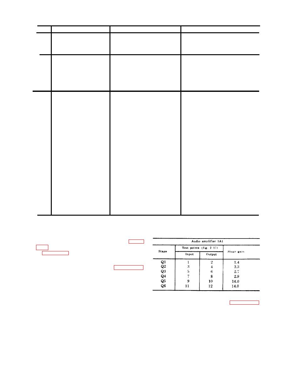
c. Stage Gain Measurements. Use the pro-
voltage. The stage gain should be as
cedures given below when either audio ampli-
listed below.
fier 1A1 or 1A2 is believed to be defective.
Stage gain test points are indicated in figures
in figures 2-1 through 2-12.
(1) For audio amplifier 1A1, connect the
equipment as shown in figure 2-17.
Adjust Audio Oscillator TS421/U
for 0.1 volt ac at 3 kilocycles (kc).
Use the ME-30B/U, and measure the
voltage between the test points,
listed in the chart below, and chassis
(2) For audio amplifier 1A2, connect the
ground. Compute the gain by divid-
equipment as shown in figure 2-18.
ing the output voltage by the input
Adjust Audio Oscillator TS-421/U
25
|
|
Privacy Statement - Press Release - Copyright Information. - Contact Us |
