 |
|||
|
|
|||
|
Page Title:
Figure 2-13. Radio set simulator, audio amplifier 1A1, voltage and resistance measurement diagram. |
|
||
| ||||||||||
|
|
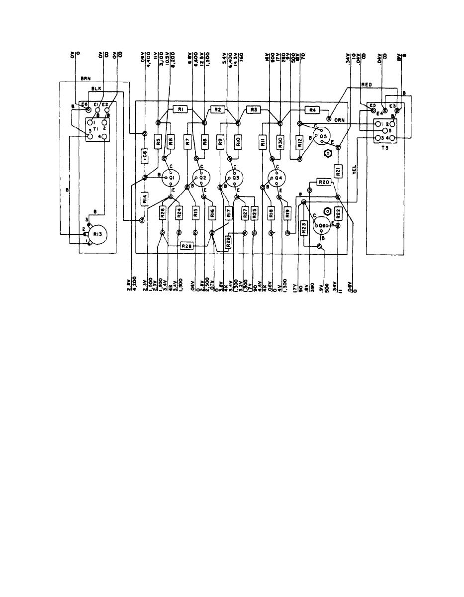 TM 11-6625-564-45
NOTES:
1.
VOLTAGE READINGS ARE ABOVE THE LINE, RESISTANCE READINGS ARE BELOW.
2. UNLESS OTHERWlSE INDICATED, ALL VOLTAGES ARE DC, AND ALL RESISTANCE
VALUES ARE IN OHMS.
3. DO NOT ATTEMPT TO MAKE RESISTANCE MEASUREMENTS WITH POWER ON
WITH MULTIMETER ME-268/U.
5. ALL DC MEASUREMENTS TAKEN FROM TEST POINT TO GROUND WITH
TM6625-564-45-50
MULTIMETER ME-268/U AND NO SIGNAL INPUT.
Figure 2-13. Radio set simulator, audio amplifier 1A1, voltage and resistance
measurement diagram.
37
|
|
Privacy Statement - Press Release - Copyright Information. - Contact Us |
