 |
|||
|
|
|||
|
|
|||
| ||||||||||
|
|
 TM 9-2815-210-34-2-2
d.
Assembly.
FRAME 1
NOTE
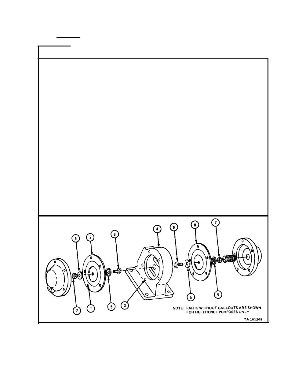
O n e of five holes (1) in
diaphragm (2) and one of
f i v e screw holes (3) in
crankcase breather valve
D i a p h r a g m can be put on
housing (4) are offset.
v a l v e housing only one
way.
L i n e up five holes (1) in new diaphragm (2) with five screw holes (3) in crank-
1.
case breather valve housing (4). Note which side of diaphragm must face out
so that holes will line up.
NOTE
Each diaphragm (2) comes with two diaphragm support
d i s k s ( 5 ) . B o t h diaphragm support disks are the same.
P u t diaphragm needle (6) through one diaphragm support disk (5). Curved-
2.
i n side of support disk must face away from diaphragm as shown.
P u t diaphragm needle (6) with diaphragm support disk (5) through hole in
3.
c e n t e r of diaphragm (2). Put diaphragm needle in from side of diaphragm
w h i c h will face in toward valve housing (4).
4.
S l i d e outer diaphragm support disk (5) over end of diaphragm needle (6).
C u r v e d - i n side of diaphragm support disk must face away from diaphragm (2)
as shown.
P u t on locknut (7).
5.
D o steps 1 through 5 again for other diaphragm (8).
6.
GO TO FRAME 2
|
|
Privacy Statement - Press Release - Copyright Information. - Contact Us |