 |
|||
|
|
|||
|
Page Title:
REMOTE CONTROL UNIT REPAIR |
|
||
| ||||||||||
|
|
 TM 9-2320-366-20-3
This task covers:
a.
Controller Removal
e. Harness Removal
b.
Controller Installation
f. Harness Installation
c.
Toggle Switch Removal
g. Follow-On Maintenance
d.
Toggle Switch Installation
INITIAL SETUP
Equipment Conditions
Materials/Parts
MHC remote control unit removed (TM 9-2320-366-10-1
Dispenser, Pressure Sensitive Adhesive Tape
or TM 9-2320-366-10-2).
(Item 20, Appendix D)
Adhesive (Item 5, Appendix D)
Nut, Self-Locking (4) (Item 175, Appendix G)
Tools and Special Tools
Tool Kit, Genl Mech (Item 46, Appendix C)
Wrench, Torque, 0-75 lb-in. (Item 90, Appendix B)
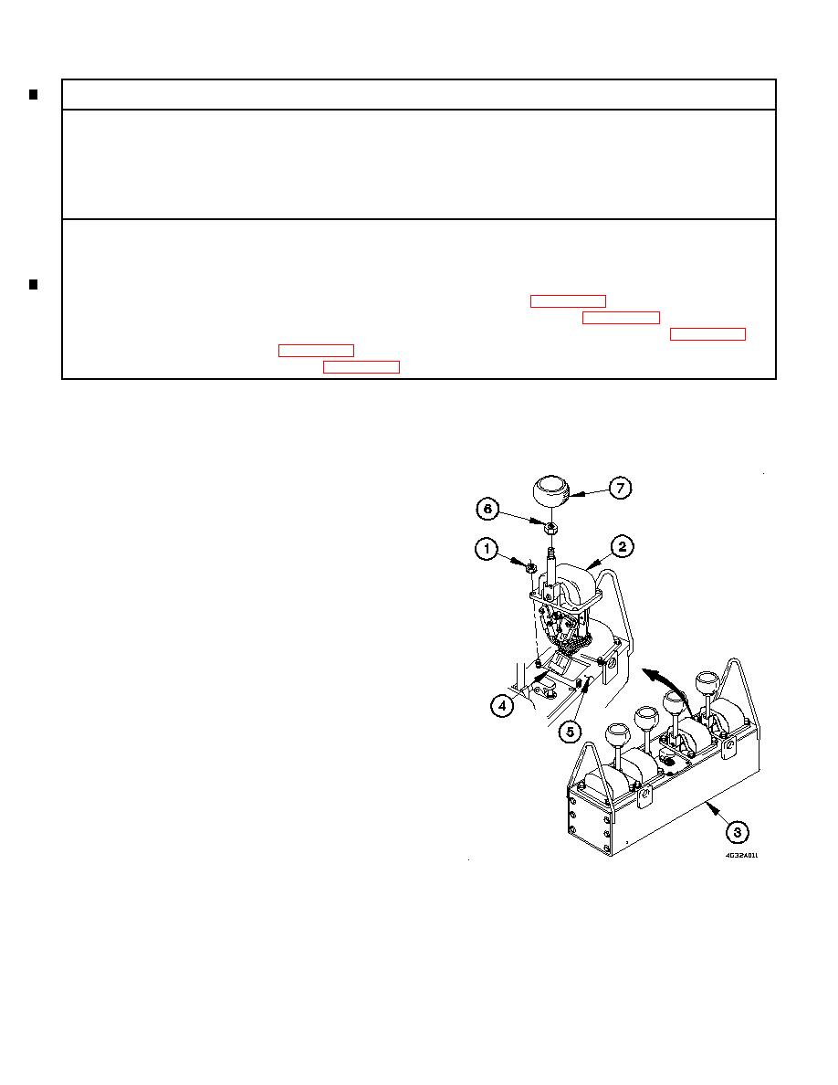
a. Controller Removal.
NOTE
All four controllers are removed the same
way. Boom Up/Down controller shown.
(1) Remove four self-locking nuts (1) from boom up/down
controller (2). Discard self-locking nuts.
(2) Remove boom up/down controller (2) from REMOTE
CONTROL UNIT (3) until connector (4) is accessible.
(3) Disconnect connector (4) from boom up/down controller
(2).
(4) Remove adhesive from seating surface (5).
(5) Loosen jam nut (6) on boom up/down controller (2).
(6) Remove knob (7) from boom up/down controller (2).
(7) Remove jam nut (6) from boom up/down controller (2).
Change 1
|
|
Privacy Statement - Press Release - Copyright Information. - Contact Us |