 |
|||
|
|
|||
|
|
|||
| ||||||||||
|
|
 TM 9-2320-366-20-3
This task covers:
a. Removal
c. Follow-On Maintenance
b. Installation
INITIAL SETUP
Equipment Conditions
Materials/Parts
Instrument panel assembly removed for access (para
Ties, Cable, Plastic (Item 69, Appendix D)
7-15).
Nut, Self-Locking (2) (Item 133, Appendix G)
Tools and Special Tools
Tool Kit, Genl Mech (Item 46, Appendix C)
Wrench, Torque, 0-75 lb-in. (Item 90, Appendix B)
a. Removal.
NOTE
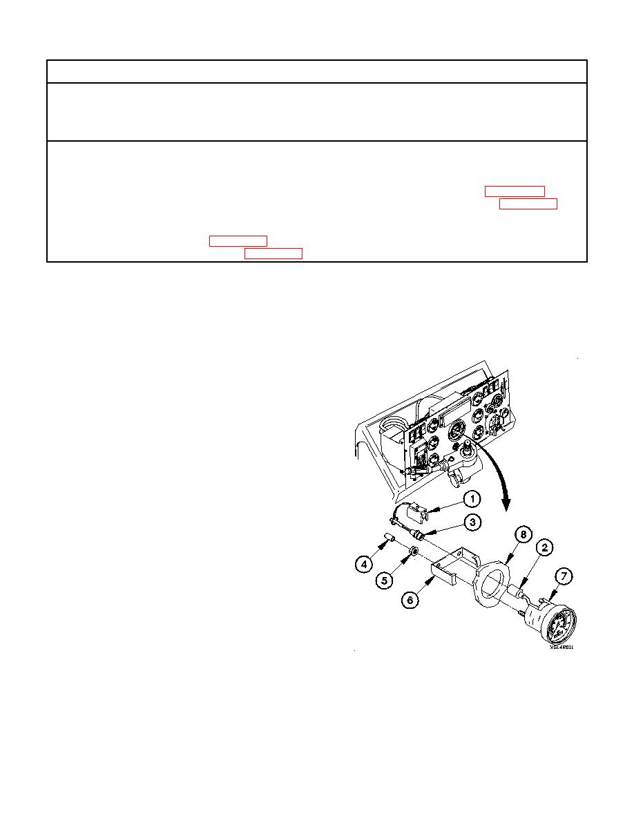
All electrical gages are removed the same
way. Speedometer shown.
(1) Disconnect connector clamp (1) from speedometer
connector (2).
NOTE
Remove plastic cable ties as required.
(2) Disconnect connector PX8 (3) from speedometer
connector (2).
NOTE
Note position of speedometer prior to
removal.
(3) Remove two protective caps (4), self-locking nuts (5),
retaining ring (6), and speedometer (7) from instrument
panel assembly (8). Discard self-locking nuts.
|
|
Privacy Statement - Press Release - Copyright Information. - Contact Us |