 |
|||
|
|
|||
|
|
|||
| ||||||||||
|
|
 TM 9-2320-279-20-1
Electrical System Maintenance instructions (Cont)
b.
Installation.
NOTE
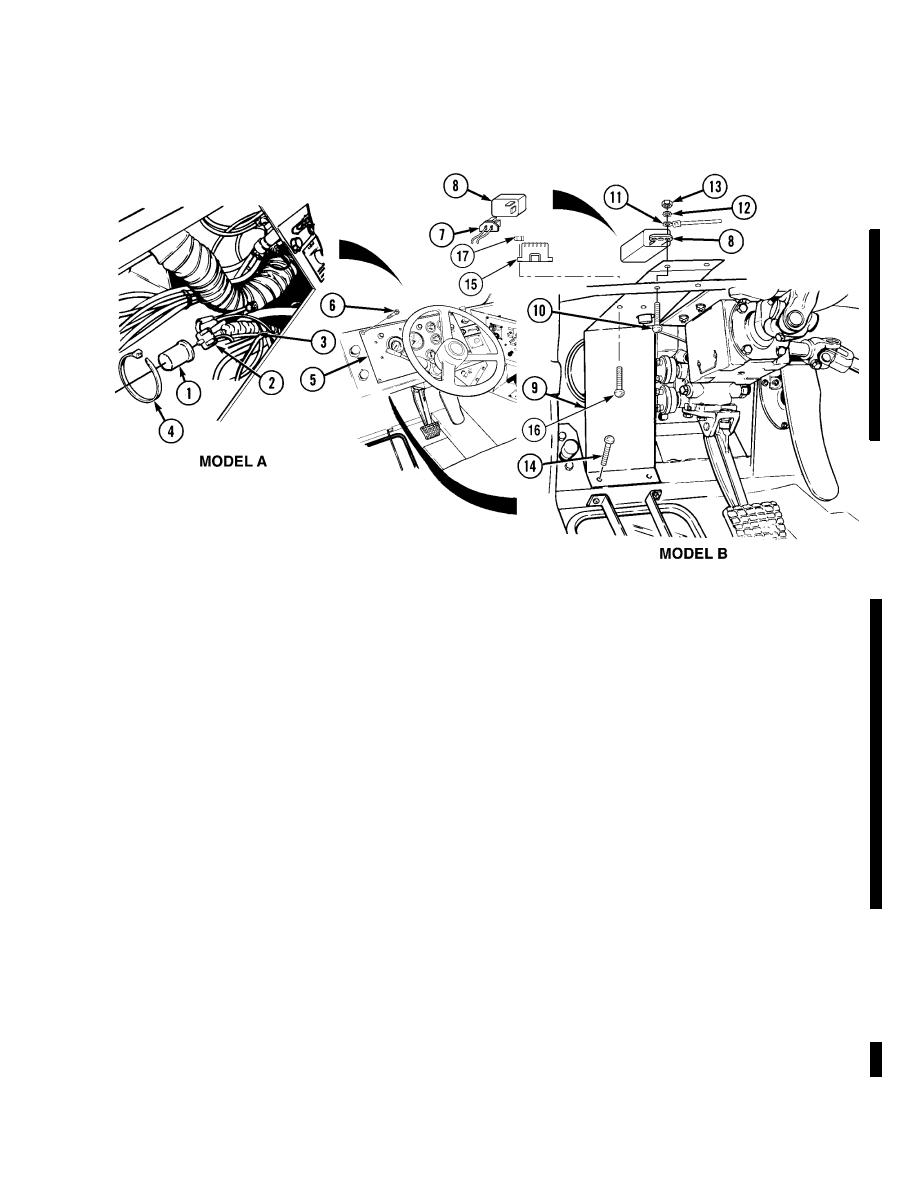
There are three kinds of flasher relays.
Model A is round and is strapped to a wire harness with a plastic cable tie.
Model B is square and is attached to the dash with a screw, lockwasher, and nut.
Model C is attached to the headlight guard with two screws and locknuts.
If a Model A relay must be replaced by a Model B relay, the top left side hole in the
headlight guard must be drilled out and the self-tapping screw replaced by a screw,
lockwasher, and nut. Also, a ground wire must be added. Route the ground wire
along the wire harness to the ground point on the ignition switch bracket. Refer to
TM 9-2320-279-24P for proper identification of parts.
For Model A, do steps (1) through (3).
For Model B, do steps (4) through (7).
For Model C, do steps (8) and (9).
(1)
Install flasher relay (1) in base (2).
(2)
Secure flasher relay (1) to wire harness (3) with plastic cable tie (4).
(3)
Install instrument panel (5) with six screws (6).
(4)
Connect electrical connector (7) to flasher relay (8).
(5)
Position headlight guard (9) and relay (8) in appropriate area under driver-side dash panel.
(6)
Install screw (10), relay (8), ground wire (11), lockwasher (12), and nut (13).
(7)
Install three screws (14).
(8)
Install flasher relay (15) on headlight guard (9) with two screws (16) and locknuts (17).
(9)
Connect electrical connector (7) to flasher relay (15).
Change 5
|
|
Privacy Statement - Press Release - Copyright Information. - Contact Us |