 |
|||
|
|
|||
|
|
|||
| ||||||||||
|
|
 TM 9-2320-279-20-1
Electrical System Maintenance Instructions (Cont)
CAUTION
Do not force adjusting screw past stops at
either end of range. Damage to voltage
regulator may result.
NOTE
Turn adjusting screw clockwise to
increase voltage, counter--clockwise
to decrease voltage.
Replace alternator if 28.02 volts
cannot be obtained.
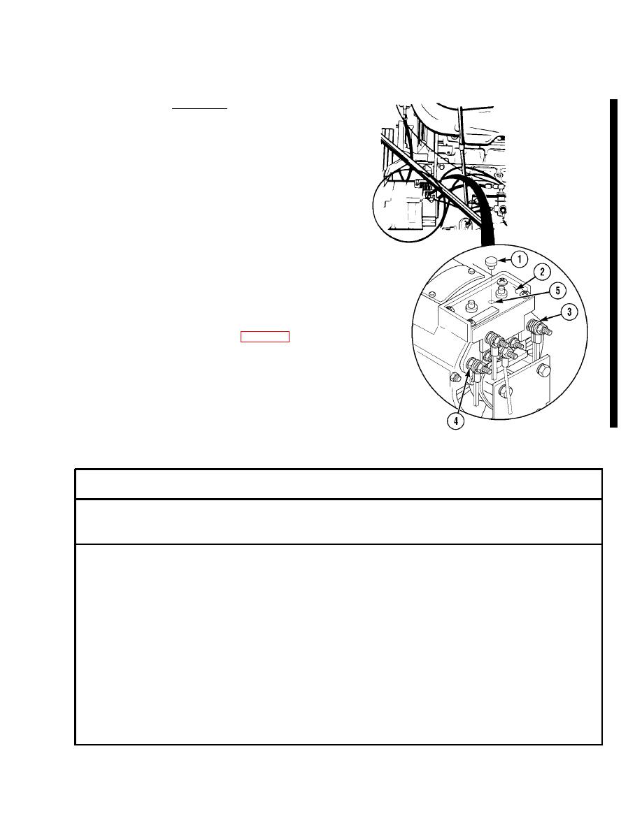
(5)
Turn adjusting screw (5) until voltage of
28.02 vdc is obtained.
(6)
Install plastic cap (1) in access hole of
cover (2).
(7)
Disconnect voltmeter test leads from
negative (--) terminal (4) and positive (+)
terminal (3).
(8)
Test alternator output (para 7-2).
b.
Follow-On Maintenance.
(1)
Shut off engine (TM 9-2320-279-10).
(2)
Install engine side panel (TM 9-2320-279-10).
(3)
Close engine cover (TM 9-2320-279-10).
END OF TASK
Section III. STARTER
This task covers:
a. Testing
b. Follow-on Maintenance
INITIAL SETUP
References
Models
None
All
Equipment Condition
Test Equipment
TM or Para
Condition Description
Multimeter NSN 6625-01-139-2512
TM 9-2320-279-10 Shut off engine.
TM 9-2320-279-10 Engine cover open.
Special Tools
TM 9-2320-279-10 Engine side panel removed.
None
Special Environmental Conditions
Supplies
None
None
General Safety Instructions
Personnel Required
None
MOS 63S, Heavy wheel vehicle mechanic (2)
Change 8
|
|
Privacy Statement - Press Release - Copyright Information. - Contact Us |