 |
|||
|
|
|||
|
|
|||
| ||||||||||
|
|
 TM 9-2320-211-20-3-2
b.
Replacement.
FRAME 1
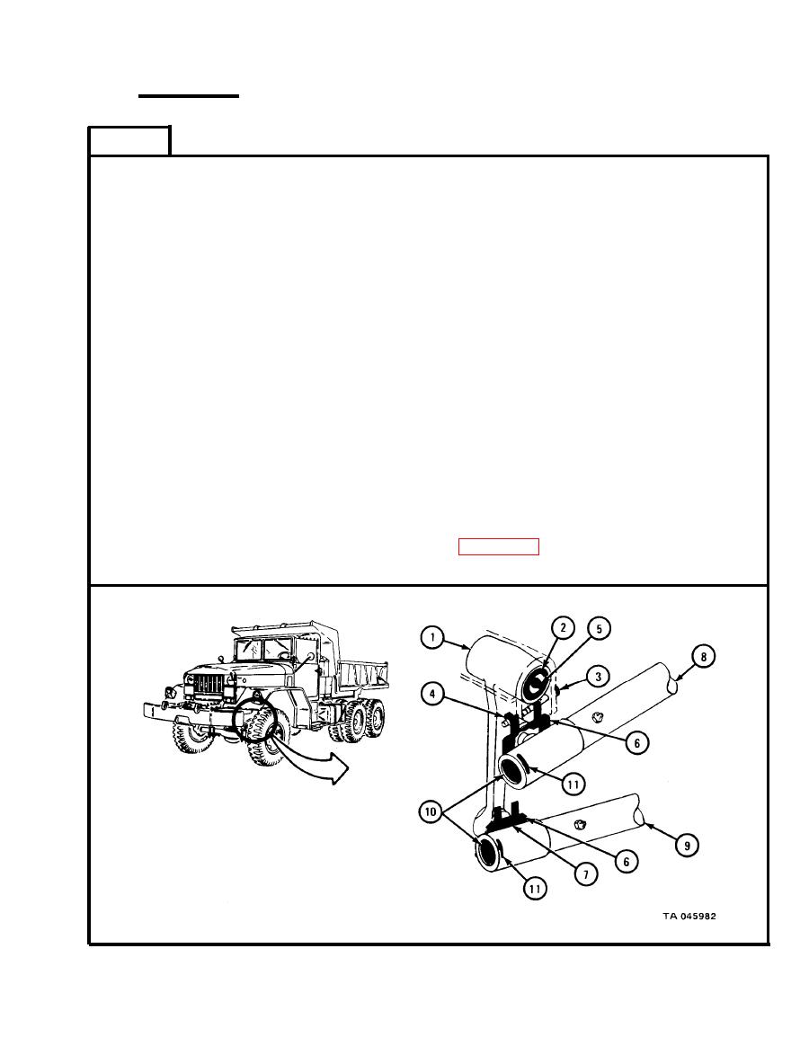
Put relay lever (1) in place as shown.
1.
2.
Using hammer and brass drift pin, tap shaft (2) through relay lever (1).
Put screw (3) in place.
3.
Using 3/4-inch wrenches, tighten nut (4).
Using 7/16-inch wrench, screw in and tighten grease fitting (5).
4.
Put dust shield with felt pad (6) on each of two ball studs (7).
5.
6.
Press upper drag link (8) onto one ball stud (7) and lower drag link (9) onto
other ball stud on relay lever (1).
Using screwdriver bit, screw in and tighten two plugs (10) into two drag
7.
links (8 and 9). Back plugs off until slot alines with holes for cotter pins
(11).
Using pliers, put cotter pin (11) through each drag link (8 and 9) and plug
8.
(10). Bend open ends of cotter pins.
Snap dust shield with felt pads (6) around each drag link (8 and 9).
9.
NOTE
Follow-on Maintenance Action Required:
1. Lubricate drag links. Refer to LO 9-2320-211-12.
2. Adjust drag links. Refer to para 14-6.
END OF TASK
|
|
Privacy Statement - Press Release - Copyright Information. - Contact Us |