 |
|||
|
|
|||
|
|
|||
| ||||||||||
|
|
 TM 5-5420-279-23
a.
Remove
(1)
De-pressurize the system. Refer to unit maintenance procedure 5-118.
(2)
Remove the left hand launch frame guard, to gain access the pinch roll/stowing manifold.
Refer to operator's TM 5-5420-279-10 Chapter 10.
NOTE
The pinch roller ball valve must be operated to release residual hydraulic pressure acting
on the rear pinch roller.
(3)
Turn the rear pinch roller ball valve lever through 90 degrees. See Appendix F page 19
figure 9. Once the pressure has been released turn the lever back through 90 degrees.
(4)
Remove the launch frame guards. Refer to operator's TM 5-5420-279-10 Chapter 10.
(5)
Release the hydraulic pressure in the articulator cylinder and the stow cylinder, refer to unit
maintenance procedure 5-123.
(6)
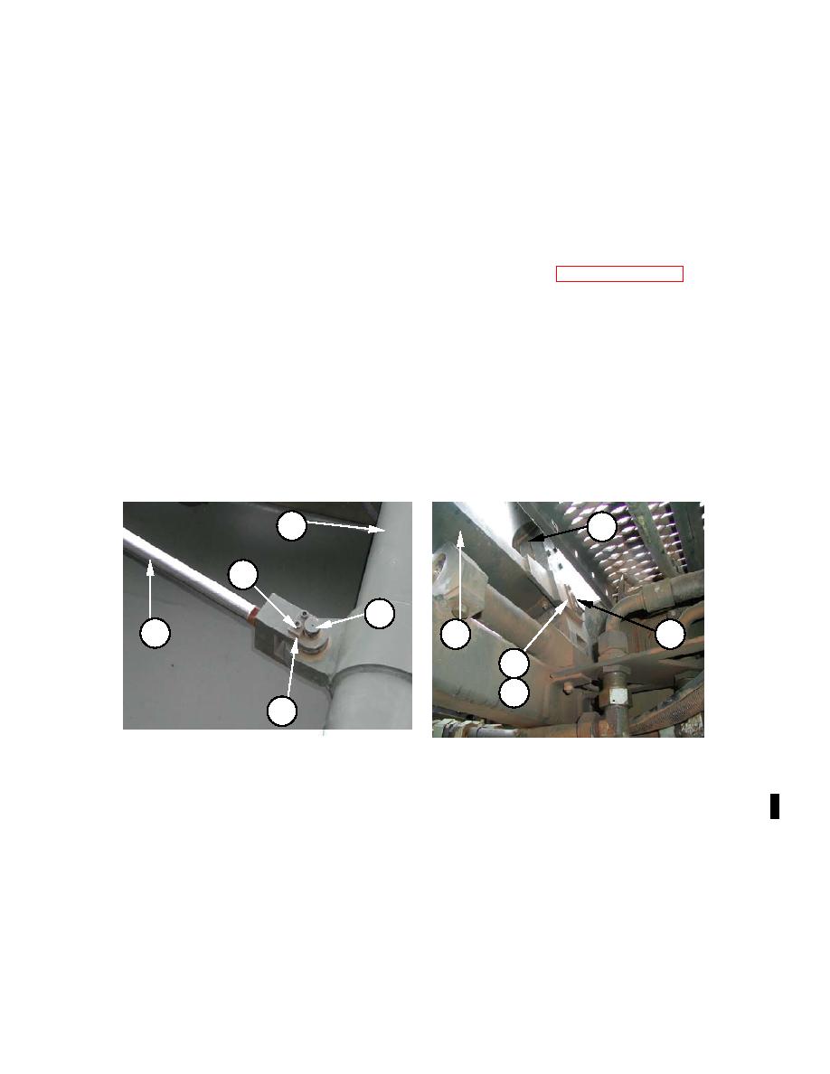
The articulator cylinder (1) is located on the launch frame.
(7)
There are three points at which the articulator cylinder is mounted to the launch frame
assembly.
i)
At the top to the beam drive assembly.
ii)
In the middle to the stow cylinder.
iii)
At the bottom to the cross member assembly.
1
1
6
5
3
4
5
6
7
7
Middle Mounting
Bottom Mounting
NOTE
Locking plate and screws should be fitted towards the centerline of the frame assembly
rather than towards the outside.
Change 1 5-183
|
|
Privacy Statement - Press Release - Copyright Information. - Contact Us |