 |
|||
|
|
|||
|
|
|||
| ||||||||||
|
|
 TM 11-6625-2609-34
(8) l/16-amp, 250-volt fuse F01A250V1-16A
3-9. Receiver Circuit Test No. 1
( p a r t of MK-1004A/ARC).
a. Test Equipment and Materials.
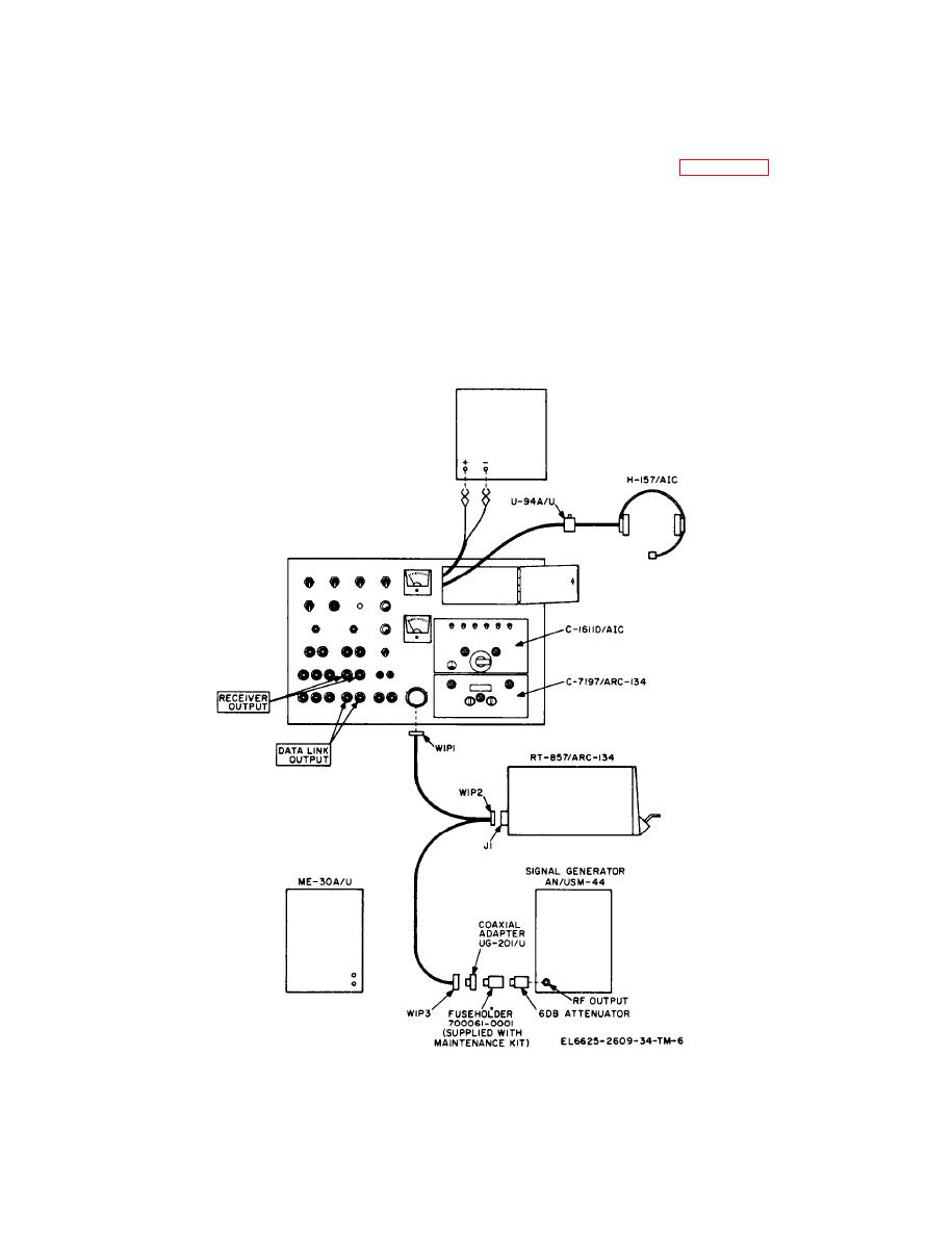
b. Test Connections and Conditions. Connect
(1)
Radio Set AN/ARC-134.
the equipment as shown in figure 3-5. Connect
(2)
Generator, Signal AN/USM-44.
the ME-30A/U to the RECEIVER OUTPUT
(3)
Power supply.
jacks on the test panel. Place the C1611D/AIC
(4)
Headset-Microphone H-157/AIC.
transmit-interphone selector switch in position 3,
(5)
Voltmeter, Electronic ME-30A/U.
the RECEIVERS 3 switch ON, all other RECEIV-
(6)
Adapter.
ERS switches to off, and position the VOL control
as required. These settings must be maintained
(7)
Fuseholder 11509A (part of MK-1004A/
during the test.
ARC).
PP-3931/FLR-9(V)
OR EQUAL
Figure 3-5. Receiver circuit, test setup.
3-10
|
|
Privacy Statement - Press Release - Copyright Information. - Contact Us |