 |
|||
|
|
|||
|
|
|||
| ||||||||||
|
|
 TM 11-6625-2609-12
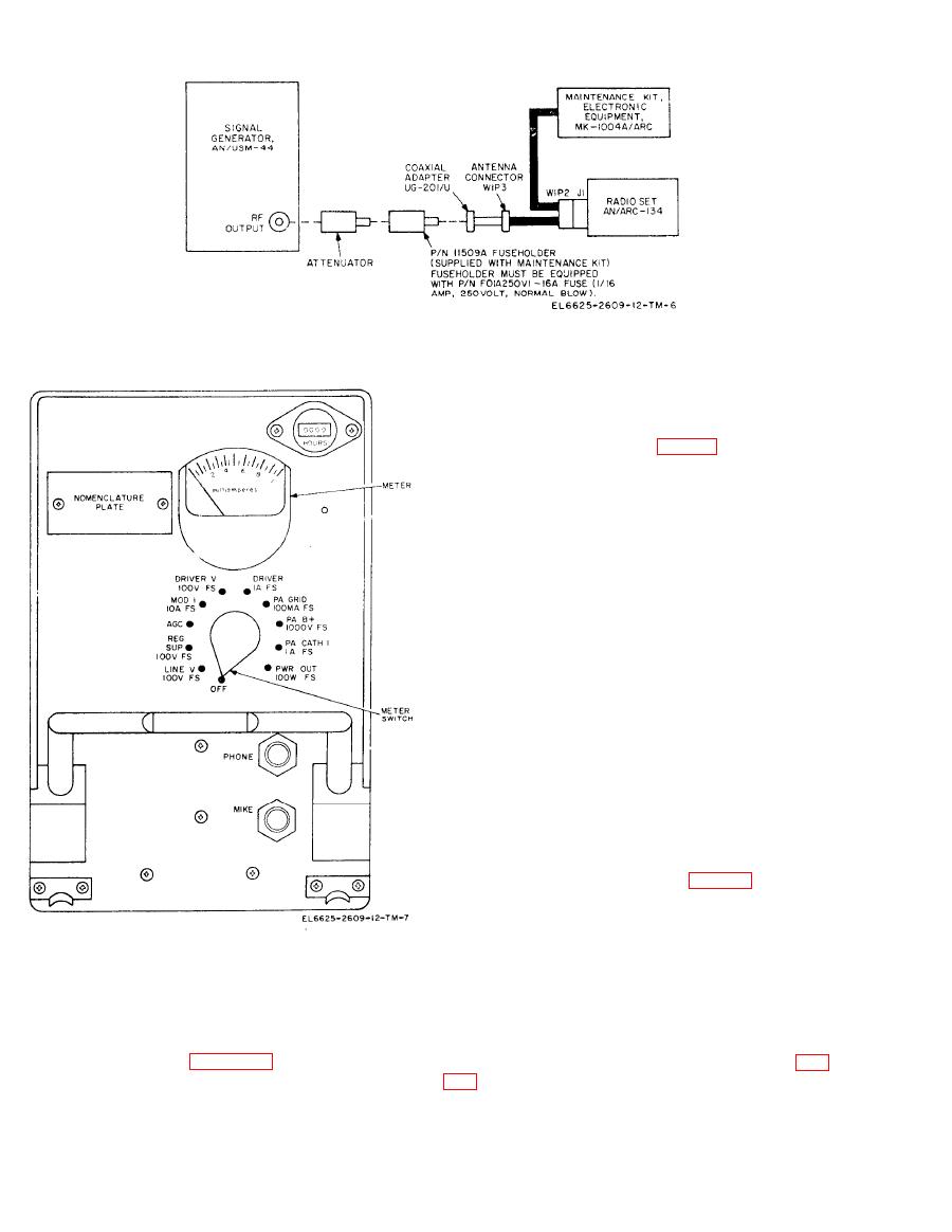
Radio Set AN/ARC-134 connected to
maintenance kit.
t h e INPUT CURRENT meter should indicate
between 2 and 3 amperes.
ARC-134 front panel to LINE V 100V FS; the
AN/ARC-134 meter should indicate 27.5 volts dc
(-20%, +10%).
The operational checks in a through h below are
given to familiarize the operator with the use of
the maintenance kit. For the complete AN/ARC-
134 test procedures, refer to TM 11-5821-277-
35.
a. Receiver Control Circuit Check at 132.5
MHz. Start the equipment as instructed in para-
graph 2-6 and proceed as follows.
(1) Connect voltmeter ME-30A/U, set to
3 0 - v o l t range, to RECEIVER OUTPUT jacks
on the maintenance kit.
CAUTION
In (2) below, be sure to connect the
11509A fuseholder between the output
receptacle of the AN/USM-44 and an-
t e n n a connector W1P3 (fig. 2-2) on
t h e maintenance kit. The fuseholder
should be equipped with a F0lA250Vl-
16A fuse. Do not press the PTT
switch on the microphone or the test
p a n e l when the very high frequency
(vhf) signal generator is connected to
the intercom control should light. The INPUT
connector W1P3.
VOLTAGE meter should indicate 27.5 volts.
b. Connect the AN/ARC-134 to the mainten-
( 2 ) Connect the AN/USM-44 to antenna
ance kit as shown in figure 2-2.
connector W1P3 on the maintenance kit (fig.
c. Set the VHF COMM OFF-PWR switch to
signal, modulated 30 percent at 1000 Hz, and set
P W R . The indicator lamps behind the VHF
the output attenuator for a 3-microvolt output.
COMM frequency counter dials should light, and
Change 1
|
|
Privacy Statement - Press Release - Copyright Information. - Contact Us |