 |
|||
|
|
|||
|
|
|||
| ||||||||||
|
|
 TM
9-2815-210-34-2-2
FRAME 4
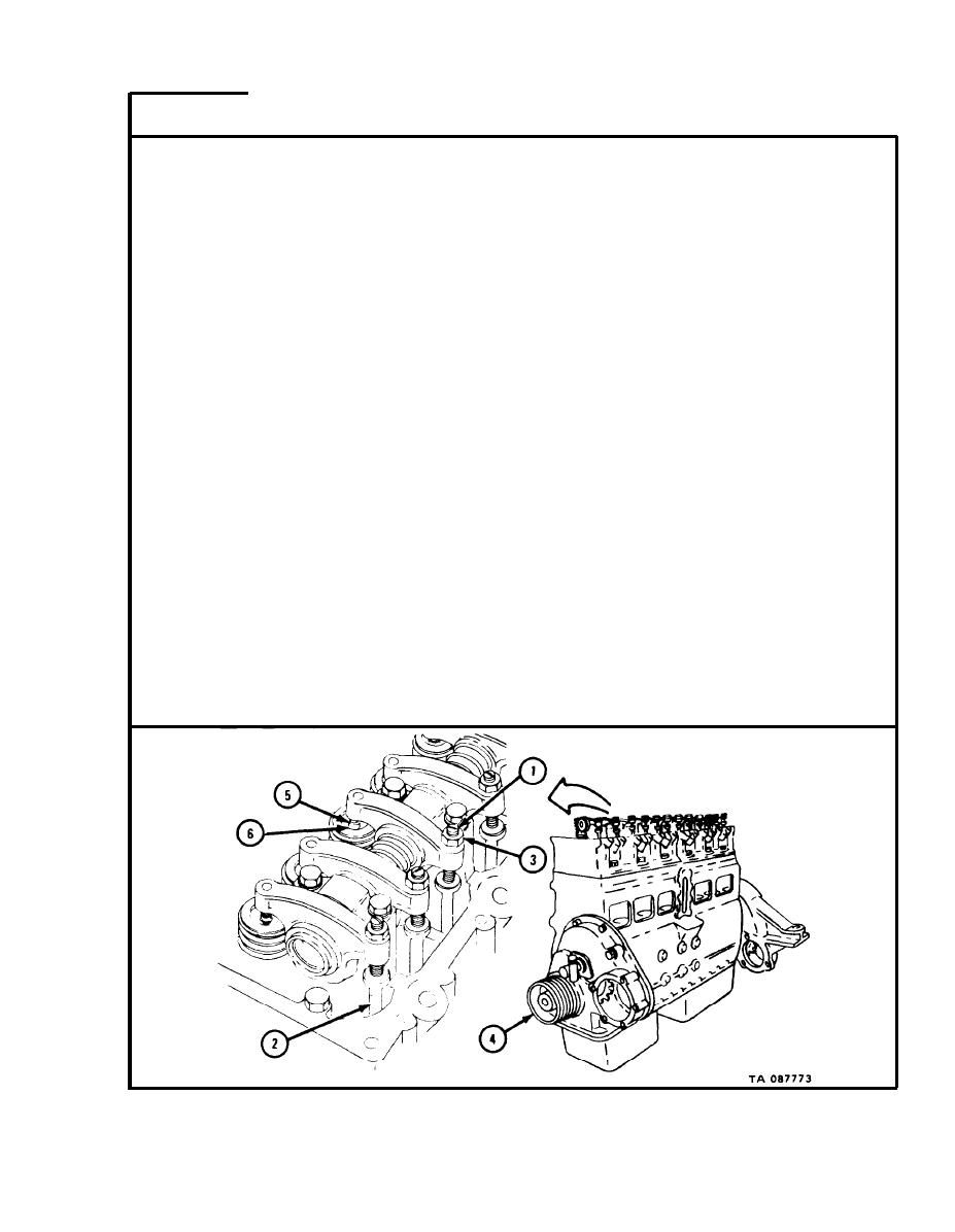
NOTE
Cylinders are called number one through six, counting
f r o m front to rear of engine. Each cylinder has one
i n t a k e valve and one exhaust valve. I n t a k e valve for
e a c h cylinder is toward front of cylinder a n d exhaust
v a l v e is toward rear of cylinder.
Turn all 1 2 adjusting screws (1) in until they just t o u c h p u s h r o d s ( 2 ) .
1.
NOTE
W h i l e turning in adjusting screws (1), you may have
t o unscrew locking nuts (3) before adjusting screw
can touch push rods (2).
2.
W a t c h push rod (2) which works cylinder number one intake valve. Using
e n g i n e - b a r r i n g wrench, turn crankshaft damper and pulley (4) until push
rod moves up as high as it will go.
3.
S l i d e 0.010-inch feeler gage between cylinder number two intake rocker
a r m pad (5) and cylinder number two intake valve stem (6).
T u r n adjusting screw (1) until feeler gage fits snugly between intake rocker
4.
a r m pad (5) and intake valve stem (6).
5.
Keep adjusting screw (1) from turning and tighten locknut (3).
6.
C h e c k that 0.010-inch feeler gage blade still fits snugly between rocker arm
pad (5) and intake valve stem (6). If feeler gage does not fit snugly, loosen
l o c k n u t (3) and do steps 2 through 6 again.
7.
D o steps 3 through 6 for cylinder number three and cylinder number six
intake valves.
GO TO FRAME 5
5-91
|
|
Privacy Statement - Press Release - Copyright Information. - Contact Us |
