 |
|||
|
|
|||
|
|
|||
| ||||||||||
|
|
 TM 9-2815-210-34-2-2
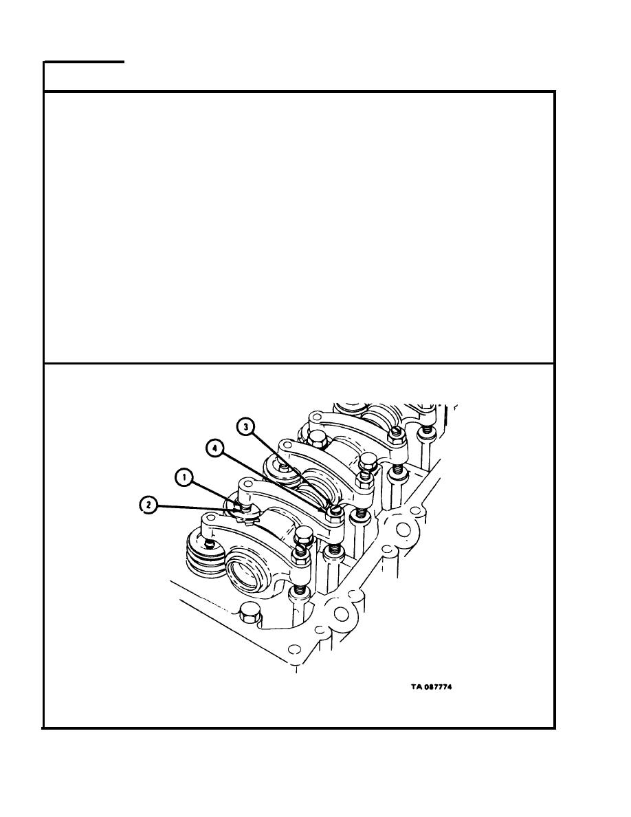
FRAME 5
NOTE
C y l i n d e r s are called number one through six counting
f r o m front to rear of engine. Each cylinder has one in-
t a k e valve and one exhaust valve. Intake valve for
e a c h cylinder is toward front of cylinder and exhaust
v a l v e is toward rear of cylinder.
1.
S l i d e 0.025-inch feeler gage between cylinder number one exhaust rocker
a r m pad (1) and exhaust valve stem (2).
2.
T u r n adjusting screw (3) until feeler gage fits snugly between cylinder
n u m b e r one exhaust rocker arm pad (1) and exhaust valve stem (2).
K e e p adjusting screw (3) from turning and tighten locknut (4).
3.
4.
C h e c k that 0.025-inch feeler gage blade still fits snugly between exhaust
r o c k e r arm pad (1) and exhaust valve stem (2). If feeler gage does not
f i t snugly, loosen locknut (4) and do steps 1 through 4 again.
5.
D o steps 1 through 4 again for cylinder number two and cylinder number
four exhaust valves.
GO TO FRAME 6
5-92
|
|
Privacy Statement - Press Release - Copyright Information. - Contact Us |
