 |
|||
|
|
|||
|
Page Title:
PISTON AND CONNECTING ROD ASSEMBLIES. |
|
||
| ||||||||||
|
|
 TM 9-2815-210-34-2-1
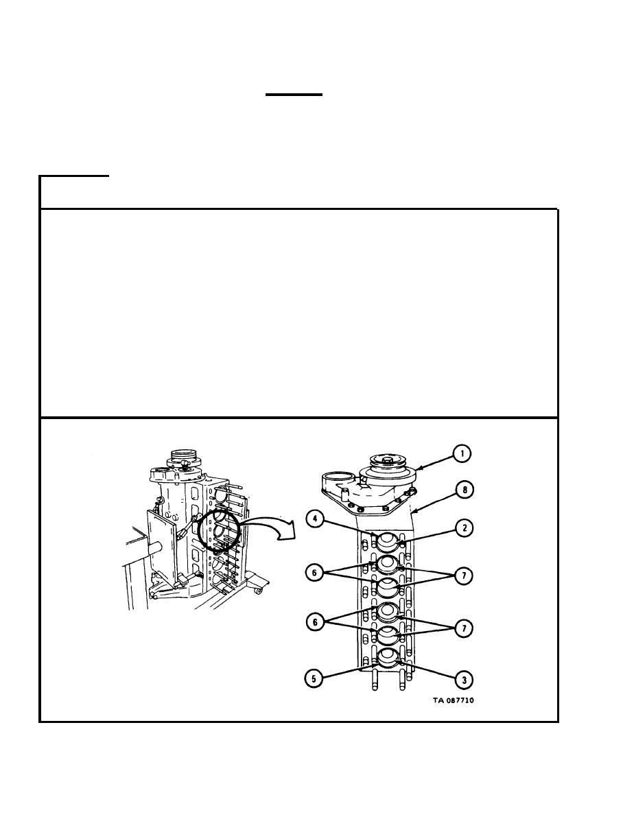
3 - 4 2 . PISTON AND CONNECTING ROD ASSEMBLIES.
CAUTION
I t is
easy to damage the equipment if you do not
know
what you are doing. Do not try to do this
task
unless you are experienced at it, or you
have
an experienced person with you.
FRAME 1
Turn engine overhaul stand so that crankshaft damper and pulley (1) are
1.
facing up.
2.
Using engine barring tool, turn crankshaft damper and pulley (1) until
cylinder number one piston and connecting rod assembly (2) and cylinder
number six piston and connecting rod assembly (3) are at bottom of stroke.
NOTE
C y l i n d e r sleeves (4, 5, and 6) and piston and con-
n e c t i n g rod assemblies (2, 3, and 7) are called by
numbers one to six counting from front to rear of
engine (8).
3.
U s i n g cylinder ridge reamer, ream out ridge at top of number one cylinder
sleeve (4) and number six cylinder sleeve (5).
GO TO FRAME 2
|
|
Privacy Statement - Press Release - Copyright Information. - Contact Us |
