 |
|||
|
|
|||
|
|
|||
| ||||||||||
|
|
 TM 9-2815-210-34-2-1
FRAME 2
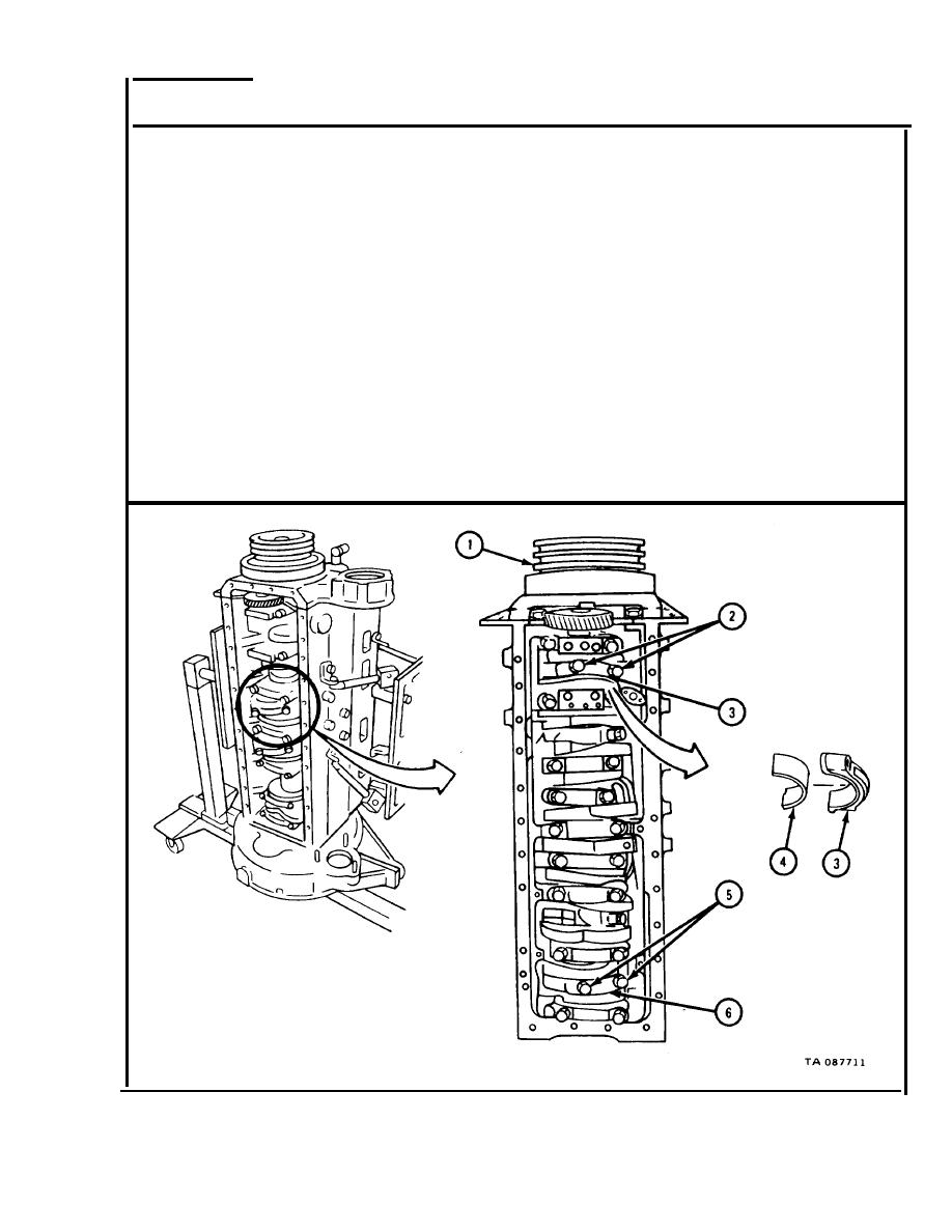
NOTE
Cylinders and piston and connecting rod assemblies are
c a l l e d by numbers one to six counting from front to
rear of engine.
1.
Turn crankshaft damper and pulley (1) until two bolts (2) holding cylinder
number one connecting rod bearing cap (3) can be easily reached, as shown.
2.
T a k e out two bolts (2) and take out cylinder number one connecting rod
bearing cap (3).
3.
Take off cylinder number one connecting rod bearing half (4). Tag it with
n u m b e r of piston and connecting rod assembly it was taken from, followed
by letter "C" for cap.
4.
T a k e out two bolts (5) and take out cylinder number six connecting rod
bearing cap (6).
5.
Do step 3 again for number six connecting rod bearing half (4).
GO TO FRAME 3
3-173
|
|
Privacy Statement - Press Release - Copyright Information. - Contact Us |
