 |
|||
|
|
|||
|
Page Title:
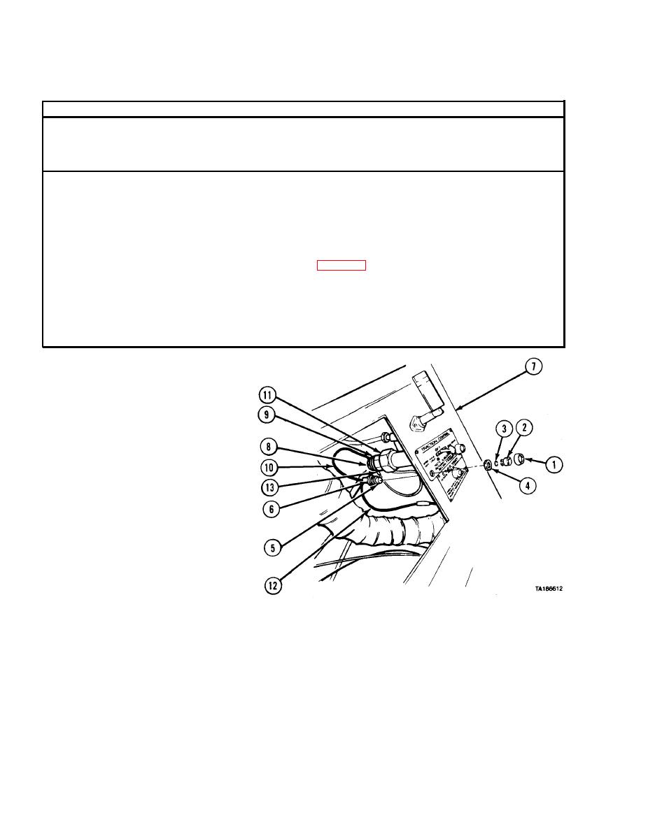
TRACTION CONTROL INDICATOR LIGHT ASSEMBLY REMOVAL/INSTALLATION. |
|
||
| ||||||||||
|
|
 TM
9-2320-279-20-1
Electrical System Maintenance Instructions (Cont)
7-99. TRACTION CONTROL INDICATOR LIGHT ASSEMBLY REMOVAL/INSTALLATION.
This task covers:
c. Follow-on Maintenance
a. Removal
b. Installation
INITIAL SETUP
References
Models
All
None
Test Equipment
Equipment Condition
None
Till or Para
Condition Description
Special Tools
Instrument panel removed.
None
Special Environmental Conditions
Supplies
None
None
General Safety Instructions
Personnel Required
None
MOS 63S, Heavy wheel vehicle mechanic
a. Removal.
NOTE
INTER-AXLE DIFF. LOCK and
8X8 DRIVE indicator lights are
removed the same way.
INTER-AXLE DIFF. LOCK
indicator light is shown.
(1) Remove two light shields (1)
and lenses (2). Remove
lenses from light shields.
Remove force rings (3) from
lenses.
(2) Remove two nuts (4).
(3) Remove two TRACTION
CONTROL indicator
lights (5) and washers (6)
from panel (7).
(4) Remove screw (8),
lockwasher (9), and
wire (10) from TRACTION
CONTROL switch (11).
(5) Cut ground wire (12) at
electrical butt connector.
|
|
Privacy Statement - Press Release - Copyright Information. - Contact Us |
