 |
|||
|
|
|||
|
Page Title:
Section III. REPAIRS AND REPLACEMENT |
|
||
| ||||||||||
|
|
 TM 11-6625-601-34
CAUTION
(3) Connect the ohmmeter negative lead to
chassis ground of the unit under test unless
Before using any ohmmeter to make
otherwise indicated.
r e s i s t a n c e measurements, check the
(4) Make all resistance measurements with-
open-circuit voltage across the ohmme-
out power applied to the test set.
ter test leads. Do not use the ohmmeter
if the open-circuit voltage exceeds 1.5
3-5. Voltage and Resistance Table
volts. Make resistance measurements
CAUTION
in the test set only as directed in the
chart below. Sensitive transistors can
Before making any voltage or resis-
be ruined if unauthorized resistance
tance measurements, refer to parag-
measurements are made.
raph 2-4 a and b. Use only authorized
test equipment or its equivalent. Dam-
b. Resistance Measurements. The resistance
a g e to transistors may result from
readings in the table (para 3-5) were obtained
improper measurement techniques or
under the conditions outlined in (1) through (4)
t h e use of unauthorized test equip-
below. Always make resistance measurements
ment.
under these conditions, or the readings may be
All voltage readings in the table are positive dc.
inaccurate.
The test points listed in the table correspond
(1) Make all resistance measurements with
to transistor connections in the equipment.
Multimeter TS-352/U, or equivalent. The open
Transistor connections are on terminal boards
circuit voltage across the ohmmeter test leads
and are identified by the following designations:
must not exceed 1.5 volts.
(2) For each resistance measurement, set
B--terminal board connection to base of transistor.
the ohmmeter range switch to the resistance
C-terminal board connection to collector of transistor.
scale specified in the chart.
E--terminal board connection to emitter of transistor.
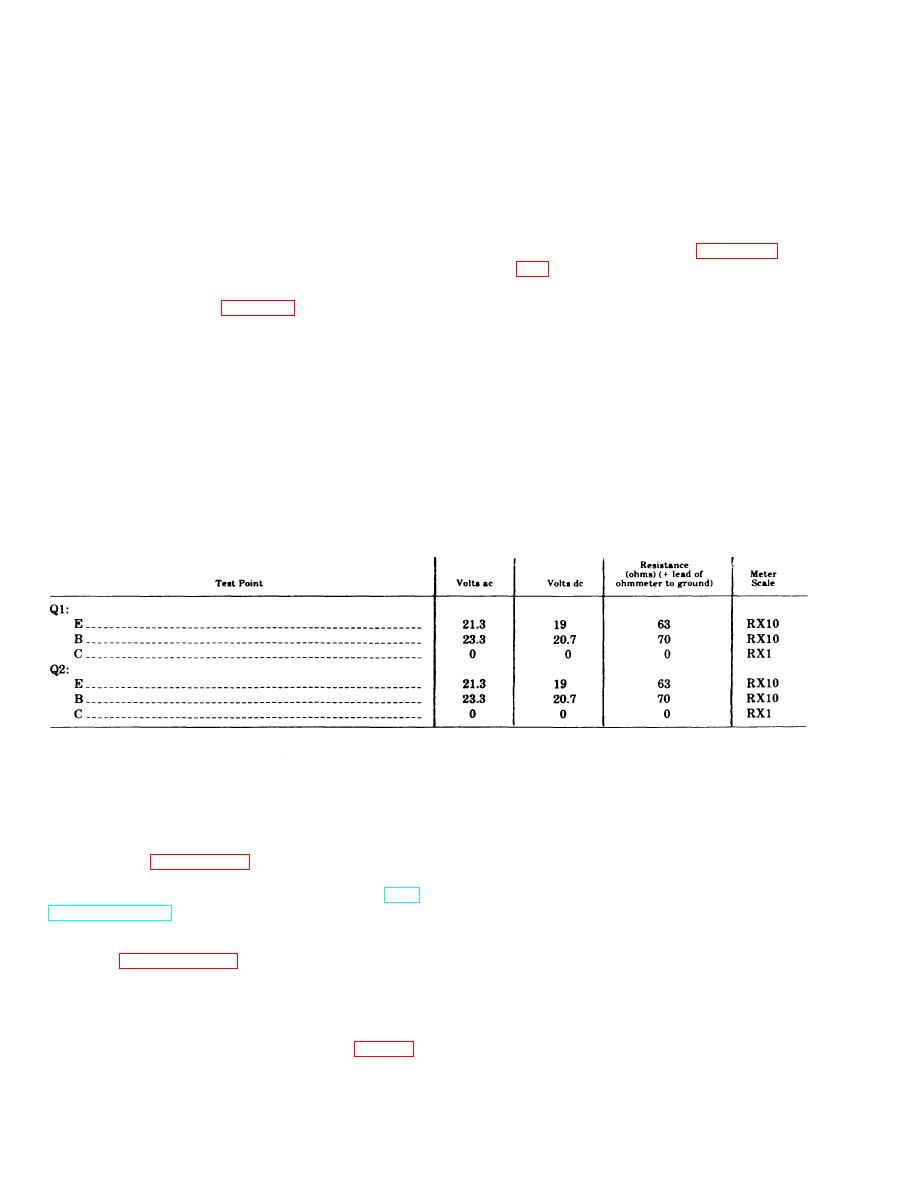
Table 3-2. Voltage and Resistance Measurements for Blower Inverter (Part of TS-1967/ARC-54)
Section Ill. REPAIRS AND REPLACEMENT
(1) Disconnect plug P1 (3) and plug P2 (4)
3-6. General Instructions
from their respective jacks on the directional
The general support maintenance procedures
coupler (5).
given in this section supplement the procedures
(2) Disconnect the two lower plugs (1 and
d e s c r i b e d in Chapter 2, Section III and the
2) from their respective jacks. (A IN21 crystal
procedures d e s c r i b e d in the operator and
diode is in each of the two jacks; be careful when
organizational maintenance m a n u a l ( T M
removing the two plugs.)
11-6625-601-12).
( 3 ) Remove the four screws and lock-
3-7. General Parts Replacement Techniques
washers (6) that secure the directional coupler
(5) to the test set chassis.
Refer to paragraph 2-7 above.
(4) Remove the directional coupler (5).
3-8. Removal and Replacement of Directional
b. Replace directional coupler DC1 as follows:
Coupler DC1 (located in TS-1967/
(1) Place the directional coupler (5) in its
ARC-54)
proper position and secure with four screws and
lockwashers (6).
as follows:
(2) Carefully connect the two lower plugs (1
3-2
|
|
Privacy Statement - Press Release - Copyright Information. - Contact Us |
