 |
|||
|
|
|||
|
Page Title:
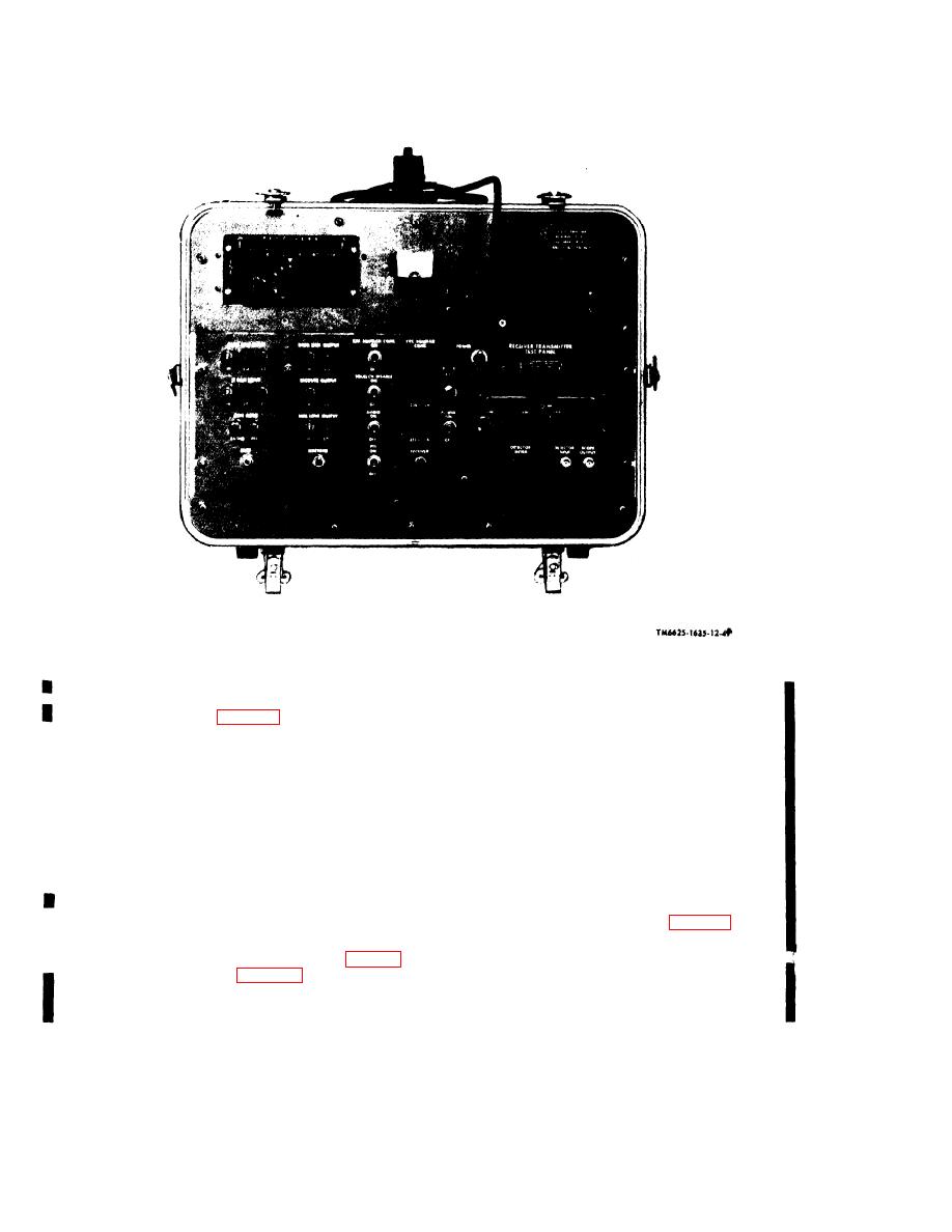
Figure 1-5.1 Test Panel, modified, front oblique view. |
|
||
| ||||||||||
|
|
 TM 11-6625-1635-12
C1
Figure 1-5.1 Test Panel, modified, front oblique view.
radio control provides power, receiver volume, i n c l u d e s a chassis, front and rear mounting
and channel-selection control functions for the plates, and a front panel. The controls and two
AN/ARC-134. A COMM TEST switch is used panel lights are mounted on the front mounting
for disabling the receiver squelch circuit during plate and extend through cutouts in the front
test procedures. A l l controls are on an edge- panel. The translucent front panel is edge-lighted
l i g h t e d plastic front panel, and the selected by the panel lights. A pin receptacle on the rear
channel frequency is indicated on an illuminated mounting plate is provided for connection of the
digital counter dial. The radio control is com- headset-microphone. Eight DZUS fasteners on
pletely inclosed except for the front panel. All the front mounting plate are used to secure the
e l e c t r i c a l connections are completed through intercom control to the test panel.
rear-mounted connectors. The unit is mounted in
f. Power Cable Assembly ( f i g . 1 - 3 ) . T h e
a cutout on the test panel front panel and is held
power cable assembly provides all power con-
in place by four quick-release fasteners (fig. 3-2). nections to the maintenance kit. The assembly,
approximately 5-feet long, consists of in-
control, included in the MK-1004/ARC
dividually insulated cables inclosed by a 48-inch
modified, is used to verify proper performance of length of sleeving. Each individual conductor is
1-10
|
|
Privacy Statement - Press Release - Copyright Information. - Contact Us |
