 |
|||
|
|
|||
|
Page Title:
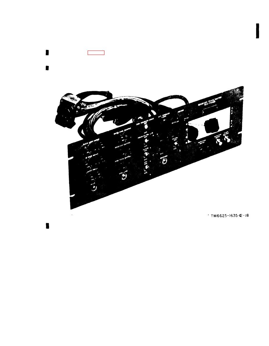
Figure 1-5. Test panel, unmodified, front oblique view. |
|
||
| ||||||||||
|
|
 TM 11-6625-1635-12
C1
f o r locking the rear cover in place. Minor
control. On the modified unit a cutout is
p r o v i d e d to mount the. intercom control. All
assemblies and running spares are in partitions
on the inside of the removable rear cover and are
e l e c t r i c a l connections to the test panel are
held in place by a metal panel which is secured
completed through cable connectors at the rear.
with three quarter-turn fasteners.
A test cable plug and antenna connector provide
a l l required connections to the AN/ARC-134.
Power is supplied to the unit by means of the
panel contains various signal input and output
power cable assembly.
j a c k s , switches, controls, and indicators. A
c u t o u t is provided for mounting the radio
Figure 1-5. Test panel, unmodified, front oblique view.
1-9
|
|
Privacy Statement - Press Release - Copyright Information. - Contact Us |
