 |
|||
|
|
|||
|
Page Title:
Description of Minor Assemblies |
|
||
| ||||||||||
|
|
 TM 11-6625-1635-12
C1
terminated with an insulated alligator clip at one
a. Power Supply PP-3931/FLR-9(V). The
PP-3931/ FLR-9(V), or equal, is required to
end and a solderless terminal lug at the other
S upply the dc power to the AN/ARC-134 under
end. The alligator clip insulators are ap-
test.
p r o p r i a t e l y marked to indicate the required
i n p u t voltage connection. In the unmodified
b . 5-Volt. A l t e r n a t i n g C u r r e n t S o u r c e
equipment, t h e third alligator clip insulator
(maintenance kit unmodified only). An
alternating current (ac) power source providing
(black] is used as a ground connection and is
5 volts (10 percent) at 1.0 ampere is required
u n m a r k e d . In the MK-1004/ARC modified. a
for the lighting circuits of the test panel and the
protective diode has been added to prevent
radio control.
dam age from reverse polarity hook-up.
c. Radio
Set
AN/ARC-l34. T h e
1-9. Description of Minor Assemblies
AN/ARC-134 is required for use with the
Special features of some of the minor assemblies
maintenance kit.
are given below (fig. 1 -3).
d. Other Equipment. A d d i t i o n a l e q u i p m e n t
a. Fuse Holder 700061-0001. The fuse
r e q u i r e d for use with the maintenance kit is
h o l d e r , with self-contained fuse,
is
used
listed below.
whenever an external signal generator is con-
(1) Signal Generator AN/USM-44.
n e c t e d to the maintenance kit antenna con-
(2) Wattmeter, Radiofrequency
nector. T h e f u s e h o l d e r p r e v e n t s p o s s i b l e
AN/URM-43A.
damage to the signal generator through ac
(3) Signal Generator AN/URM-127.
cidental keying of the AN/ARC-134 trans-
( 4 ) Multimeter TS-352B/U.
mitter.
(5) Microphone M-52A/U (maintenance
b . Radio Frequency Detector. T h e r a d i o
kit unmodified only).
frequency (RF) detector is used to observe
( 6 ) Headset, Electrical
H-216/U
with
m o d u l a t i o n during adjustments to the RF ex-
Cord
CD-307
(maintenance
kit
unmodified
or
driver
stages
in
the
citer/amplifier
only).
AN/ARC-134
transmitter
circuits.
(7) Coaxial Adapter UG-201/U.
c. Attenuator. The attenuator is connected to
( 8 ) Capacitor, 50 microfarads (f). 25
the external signal generator output to provide a
v o l t s direct current (dc), Sprague Type TL-
proper signal input level to the AN/ARC-134
1200, or equal.
during test procedures.
( 9 ) C o a x i a l C o n n e c t o r U G - 8 8 / U (two
d . T u n i n g T o o l . The tuning tool is used
required).
w h e n e v e r it is necessary to adjust the power
( 1 0 ) RG-58 coaxial cable (as required).
amplifier grid and plate coils in the AN/ARC-
134 transmitter circuits.
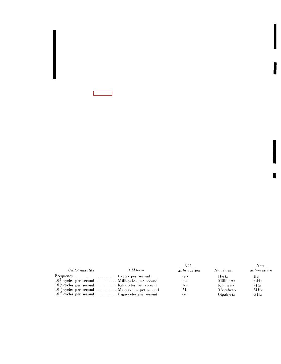
1-11. Use of Term Hertz
e. Adapter. The adapter is used to connect
The National Bureau of Standards has officially.
the external signal generator, oscilloscope, and
adopted the term Hertz (Hz) to replace cycles
l o a d wattmeter during transmitter test or ad-
per second (cps). The chart below provides the
justment procedures.
equivalents of the unit/quality terms and the
l i s t of approved abbreviations that are used
1-10. Additional Equipment Required
t h r o u g h o u t the manual.
The following equipment is not supplied as part
of the maintenance kit, but is required for use
with it.
1-11
|
|
Privacy Statement - Press Release - Copyright Information. - Contact Us |
