 |
|||
|
|
|||
|
Page Title:
FLAME HEATER NOZZLE AND VALVE ASSEMBLY (SIDE-MOUNTED SYSTEM). |
|
||
| ||||||||||
|
|
 TM 9-2815-210-34-2-2
4-74. FLAME HEATER IGNITION UNIT (SIDE-MOUNTED SYSTEM). For procedures
t o repair the flame heater side-mounted ignition unit, refer to flame heater ignition
unit (covered system), para 4-65c.
4-75. FLAME HEATER WIRING HARNESS AND ELECTRICAL LEAD ASSEMBLY (SIDE-
MOUNTED SYSTEM). For procedures to repair the side-mounted heater wiring
h a r n e s s , refer to covered flame heater wiring harness, para 4-67b.
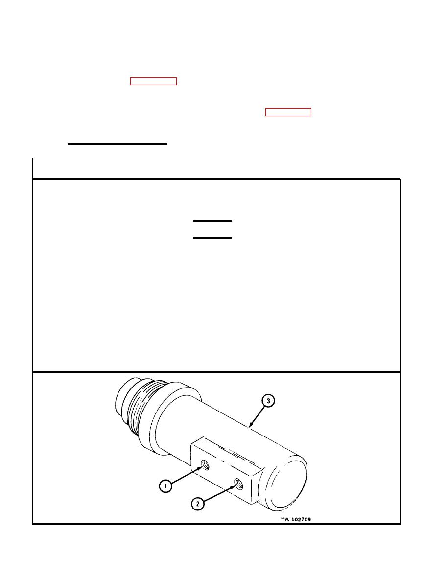
4-76. FLAME HEATER NOZZLE AND VALVE ASSEMBLY (SIDE-MOUNTED SYSTEM).
a.
C l e a n i n g and Inspection.
FRAME
1
1.
Leave felt fuel line filters in fuel inlet (1) and outlet (2) openings in place.
2.
P l u g nozzle and valve assembly fuel inlet (1) and outlet (2) openings with p i p e
plugs.
WARNING
D r y cleaning solvent is flammable. Do not use
near an open flame. K e e p a fire extinguisher
n e a r b y when solvent is used. Use only in well-
v e n t i l a t e d p l a c e s . Failure to do this may result
i n injury to personnel and damage to equipment.
3.
C l e a n nozzle and valve assembly (3) with dry cleaning solvent. Take off
h e a v y carbon deposits with a stiff brush.
4.
C h e c k that nozzle and valve assembly fuel inlet (1) and fuel outlet (2) threads
are not crossthreaded.
5.
C h e c k that nozzle and valve assembly (3) is not cracked or damaged. Get a
new nozzle and valve assembly if it is cracked or damaged.
END OF TASK
|
|
Privacy Statement - Press Release - Copyright Information. - Contact Us |