 |
|||
|
|
|||
|
|
|||
| ||||||||||
|
|
 TM
9-2815-210-34-2-2
d.
Assembly.
FRAME
1
NOTE
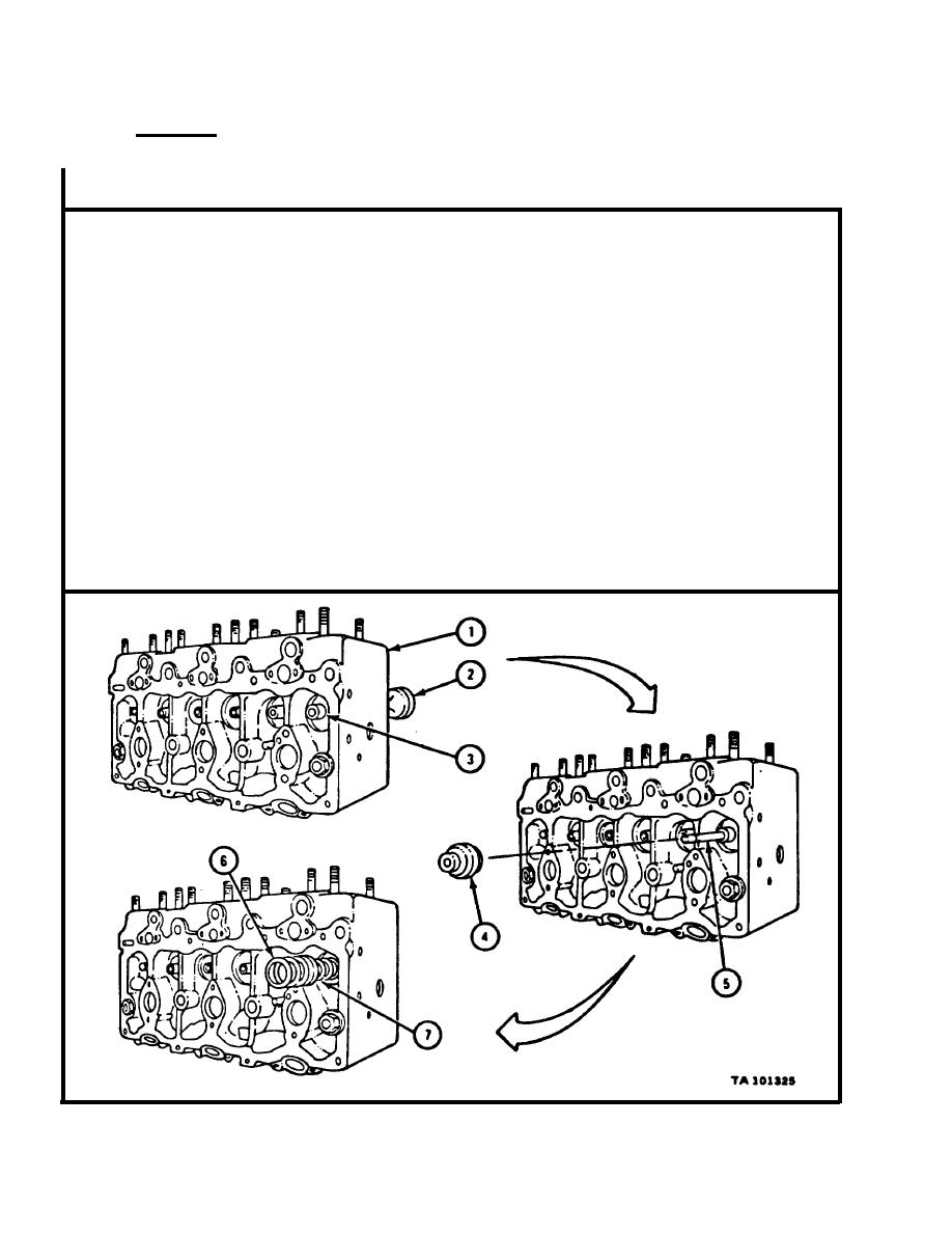
V a l v e s must be put back in cylinder head (1) in the
s a m e place they were taken from.
T a s k shown is for an exhaust valve (2). Task is the
s a m e for intake valves.
P u t exhaust valve (2) through exhaust valve guide (3) in cylinder head (1)
1.
as shown.
P u t valve rotor (4) over valve stem (5) and slide it all the way in. Spring
2.
s e a t side of rotor should face outward as shown.
NOTE
Outer valve spring (6) must be put back so that end
w i t h tightly wound coils faces cylinder head (1).
P u t inner valve spring (7) over valve stem (5). Put outer valve spring (6)
3.
over inner valve spring.
GO TO FRAME 2
|
|
Privacy Statement - Press Release - Copyright Information. - Contact Us |