 |
|||
|
|
|||
|
|
|||
| ||||||||||
|
|
 TM
9-2815-210-34-2-1
E n g i n e s LDS-465-1 and LDS-465-1A.
b.
CAUTION
Do not make a punch mark anywhere on pressure plate
a s s e m b l y (1) except where pressure plate assembly is
f l u s h with rim of flywheel (2). Pressure plate assembly
could be bent.
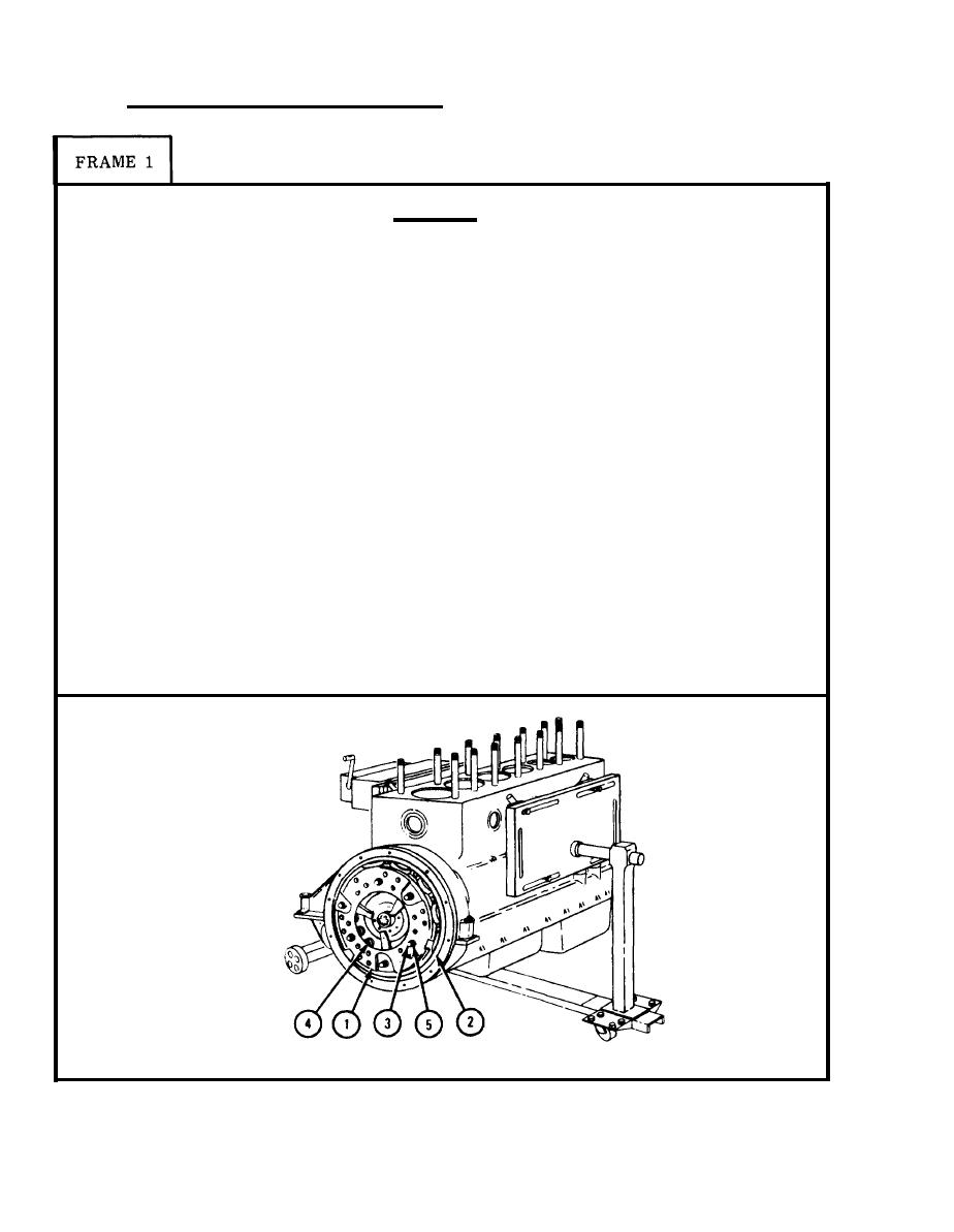
M a k e a punch mark on pressure plate assembly (1) and rim of flywheel (2)
1.
as shown. B o t h marks should be next to each other so pressure plate as-
s e m b l y and flywheel can be alined during engine assembly.
NOTE
There are many holes in pressure plate assembly (1).
O n l y three holes have a threaded sleeve behind them
f o r r e t a i n i n g s c r e w s ( 3 ) . T h e location of these holes
i s different on different pressure plate assemblies.
T h e right holes may be hard to find because threaded
sleeves are inside springs (4).
U s i n g strong light, look through big hole in center of pressure plate assembly
2.
( 1 ) . Find the three holes with threaded sleeves behind them.
P u t 3/8 - 16 x 2 1/4-inch retaining screw (3) and 1 1/4-inch outside
3.
d i a m e t e r , 1 /8-inch thick flat washer (5) into the three holes found in
step 2. T i g h t e n three retaining screws (3) evenly to take spring pressure
o f f clutch disk on flywheel (2).
GO TO FRAME 2
TA 087691
|
|
Privacy Statement - Press Release - Copyright Information. - Contact Us |