 |
|||
|
|
|||
|
|
|||
| ||||||||||
|
|
 TM 9-2320-279-20-1
Electrical System Maintenance Instructions (Cont)
7-94.
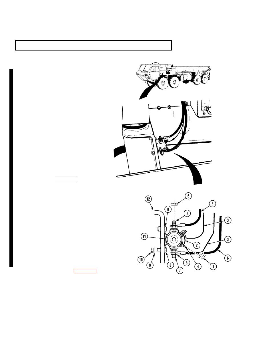
STARTER RELAY REMOVAL/INSTALLATION (CONT).
a.
Removal.
NOTE
Only M1977 CBT model vehicles
contain a diode on starter relay.
Note position of leads before
disconnecting diode.
Tag and mark wires before removing.
(1)
Remove two nuts (1), diode (2), and
wires (3) from studs (4).
(2)
Remove two nuts (5) and wires (6)
from studs (7).
(3)
Remove two screws (8),
lockwashers (9), and nuts (10).
(4)
Remove starter relay (11) from
front engine support (12).
b.
Installation.
(1)
Place starter relay (11) on front
engine support (12).
(2)
Install two screws (8),
lockwashers (9), and nuts (10).
WARNING
Adhesives, solvents, and sealing compounds can burn
easily, can give off harmful vapors, and are harmful
to skin and clothing. To avoid injury or death, keep
away from open fire and use in well-ventilated area.
If adhesive, solvent, or sealing compound gets on skin
or clothing, wash immediately with soap and water.
NOTE
Apply electrical sealant to exposed wire
connectors after installing connectors.
(3)
Install two wires (6) on studs (7) with
nuts (5).
(4)
Install two wires (3) and diode (2) on
studs (4) with nuts (1).
c.
Follow-on Maintenance.
(2) Install engine side panel (TM 9-2320-279-10).
(3) Close engine cover (TM 9-2320-279-10).
(5) Shut off engine (TM 9-2320-279-10).
END OF TASK
Change 7
|
|
Privacy Statement - Press Release - Copyright Information. - Contact Us |