 |
|||
|
|
|||
|
|
|||
| ||||||||||
|
|
 TM
9-2320-279-20-1
Electrical System Maintenance Instructions (Cont)
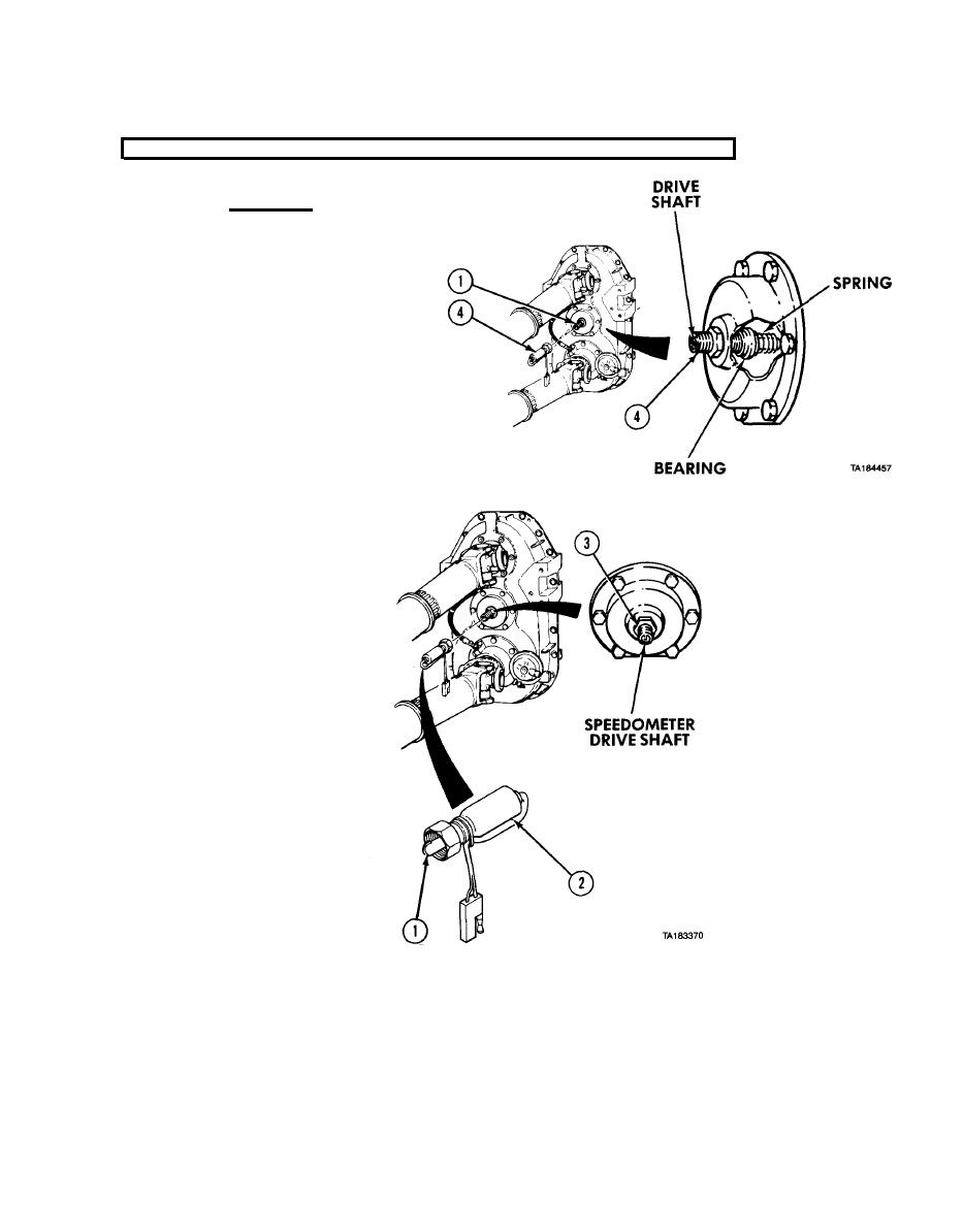
7-81. SPEEDOMETER SENDING UNIT REMOVAL/INSTALLATION (CONT).
CAUTION
Do not pull drive shaft more
than 0.50-in. (13 mm) out of
sleeve. Spring and bearing
behind sleeve can fall into end
cap and cause damage to
equipment. If spring and bearing
fall into end cap, notify the
supervisor.
(2) Remove speedometer sending
unit (3) from reducer tube (4).
b. Installation.
(1) Line up drive tang (1) of speedometer sending unit (2) with slot on drive shaft in reducer
tube (3).
(2) Install speedometer sending unit (2) on reducer tube (3) and tighten.
|
|
Privacy Statement - Press Release - Copyright Information. - Contact Us |