 |
|||
|
|
|||
|
Page Title:
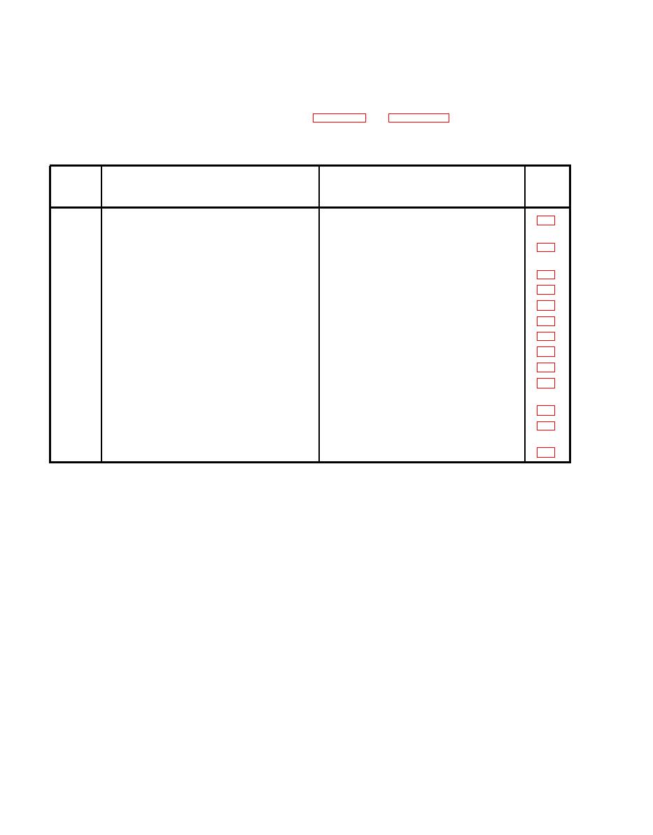
Table 7-1. Tanker Conduit Tubing |
|
||
| ||||||||||
|
|
 TM
9-2320-279-20-1
Electrical System Maintenance Instructions (Cont)
tubing sections.
Table 7-1. Tanker Conduit Tubing
Refer
To
Tube
To
Figure
From
No.
Main Junction box (a)
Chassis Wiring Harness (inside left frame
1
rail, single wire plug)
Chassis Wiring Harness (inside left
2
Main Junction Box (a)
front rail, four wire plug)
Clearance lights (on front of tank)
3
Main Junction Box (a)
Tank Level Sensor Adjuster (b)
4
Main Junction Box (a)
Tank Level Sensor (on top of tank)
5
Tank Level Sensor Adjuster (b)
Control Junction Box (c)
6
Main Junction Box (a)
Control Junction Box (c)
7
Main Junction Box (a)
Auxiliary Pump Junction Box (d)
Control Junction Box (c)
8
Right Module Interior Light (e)
9
Control Junction Box (c)
(Right) Side and Rear Clearance
Right Module Interior Light (e)
10
Lights (f)
Left Module Interior Light (g)
11
Right Module Interior Light (e)
(Left) Side and Rear Clearance
Left Module Interior Light (g)
12
Lights (h)
Three Center Rear Clearance Lights (j)
Left Module Interior Light (g)
13
7-182
|
|
Privacy Statement - Press Release - Copyright Information. - Contact Us |