 |
|||
|
|
|||
|
|
|||
| ||||||||||
|
|
 TM 9-2320-279-20-1
Vehicle
Operation
Systems
(Cont)
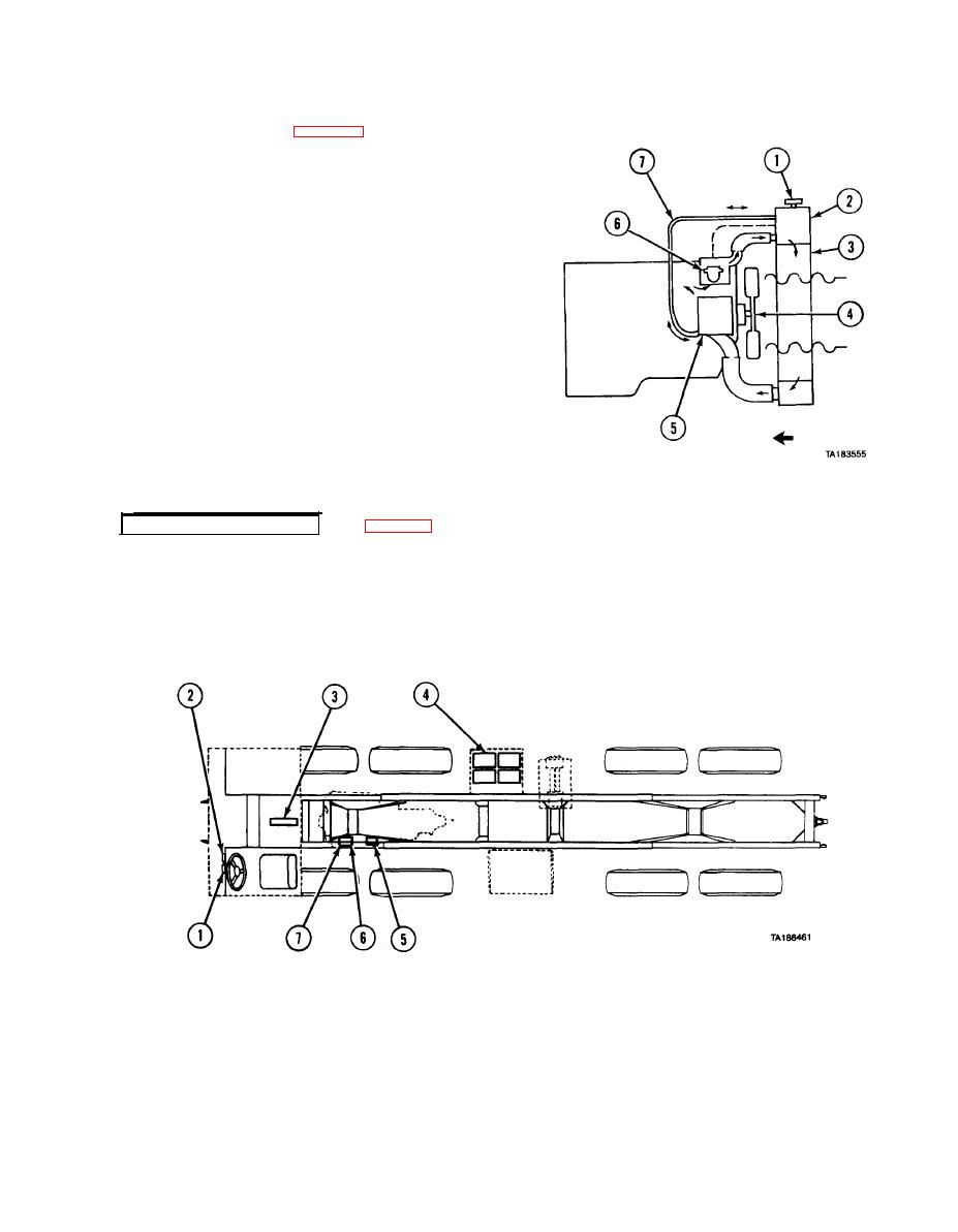
type cooling system protects the engine by
r e m o v i n g heat generated during the combustion
process. Pressure within the cooling system is
regulated by a pressure release in the radiator
filler cap (1). The hot coolant flows from the
engine to the top radiator
tank (2) and through the radiator core (3) where a
stream of air removes heat. This stream of air is
drawn through the core by an air-activated fan (4).
A water pump (5) draws the coolant from the
bottom of the radiator and pushes it through the
engine repeating the cooling process.
T h e r m o s t a t s (6), mounted in each coolant outlet
e l b o w , remain closed until the coolant approaches
a predetermined temperature at which time they
o p e n . When the coolant temperature drops below
the thermostat rating, they close. An air vent
line (7) between the radiator (2) and the water
pump inlet removes air trapped in the engine
when the cooling system is being filled.
Cooling
System
1-17. ELECTRICAL SYSTEM.
by a battery gage (1) and an ammeter (2) located on the dash panel inside the drivers compartment. Circuit
breakers (3) located in the cab protect the main circuits. Electrical power is provided by four 12-volt
series-parallel connected batteries (4). Power is distributed throughout the vehicle by wiring harnesses.
The harnesses are interconnected by pin connectors. Connectors are provided at the rear of the vehicle to
supply power for towed loads. A heavy duty starting motor (5) is mounted on the engine flywheel housing
and provides the cranking power necessary for starting the engine. The voltage regulator (6) is mounted on
the belt driven alternator (7) and maintains a 24-volt level for battery charging.
|
|
Privacy Statement - Press Release - Copyright Information. - Contact Us |