 |
|||
|
|
|||
|
Page Title:
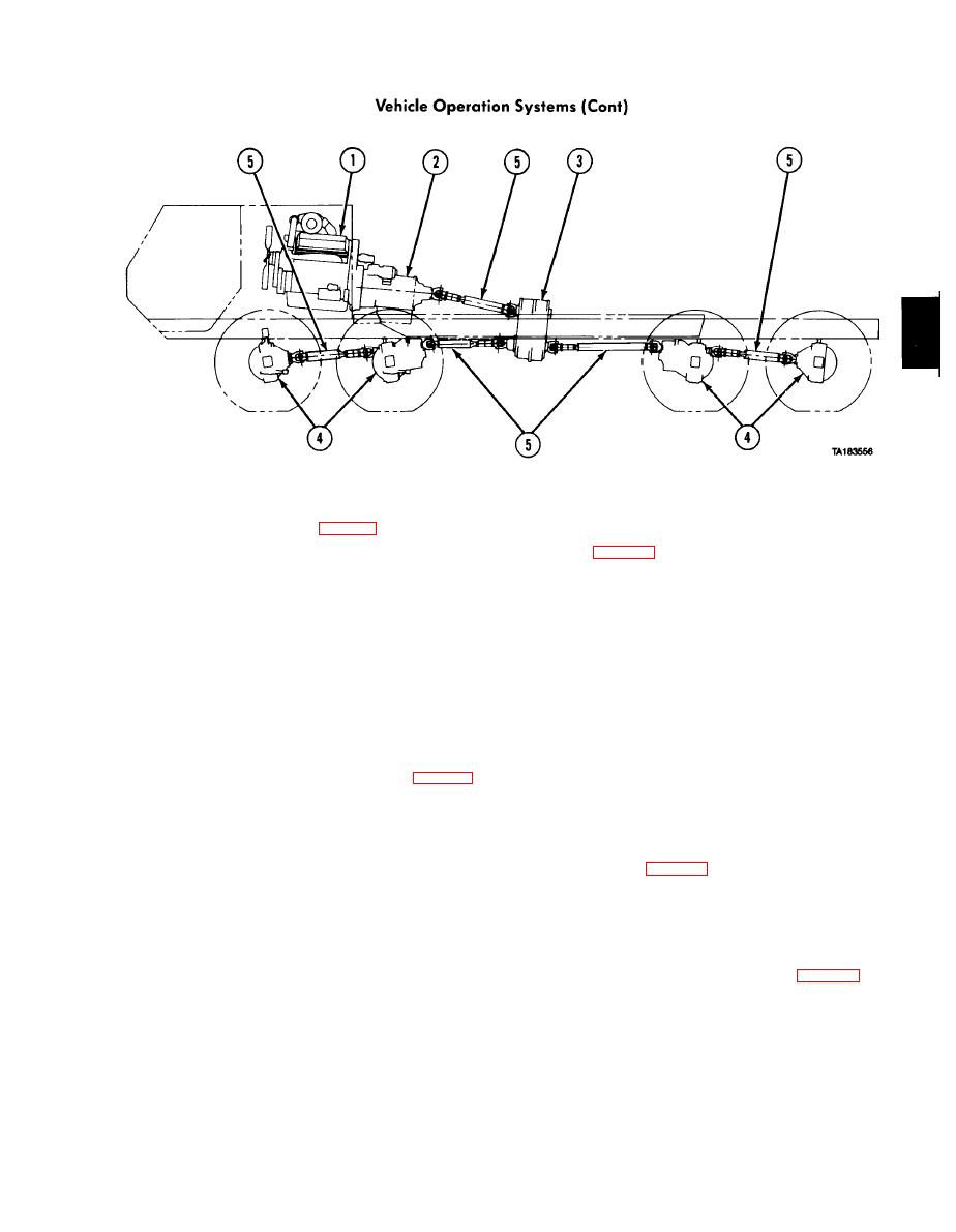
Figure 1-9. Power Train. |
|
||
| ||||||||||
|
|
 TM 9-2320-279-20-1
b . A u t o m a t i c T r a n s m i s s i o n . The automatic transmission, (2, fig. 1-9) provides four speeds forward
a n d one reverse.
(1) Drive (D) is used for all normal driving conditions. The vehicle will start moving in 1st gear, and
as the accelerator is depressed, transmission will upshift to 2nd gear, 3rd gear and 4th gear automatically.
As the vehicle slows down, the transmission will downshift to the correct gear automatically. Placing the
range selector lever in the 3 or 2 position will prevent the transmission from upshifting past the 3rd or 2nd
gear, respectively. This is useful if road or load conditions require low gear operation. When conditions
improve, the range selector lever can be returned to the normal (D) driving position. TM 9-2320-279-10
provides full operating instructions for the transmission.
(2) The transmission includes an electrically controlled power takeoff (PTO). The PTO provides
power to a hydraulic pump, which powers the vehicle's hydraulic system. The hydraulic system operates
t h e self-recovery winch, the material handling crane, the heavy duty recovery winch, and the pumping
e q u i p m e n t , depending on how the vehicle is equipped.
c. Transfer case. The transfer case (3, fig. 1-9), connects the drive train to the No. 1 and No. 2 axles
when 8-wheel drive is needed. The transfer case has two gear ratios (high and low) and neutral. Because
the gears are not synchronized, the vehicle must be stopped before the transfer case can be shifted
between ranges. Engagement of the transfer case in low range will automatically engage the drive train to
the front axles.
d . T a n d e m A x l e s a n d S u s p e n s i o n . Front and rear tandem axles (4, fig. 1-9) are single reduction,
full floating axle shaft type. The front tandem provides steering. The rear tandem is nonsteering. Both
front and rear tandems are equipped with wheel differentials and interaxle differentials. The interaxle
differentials have driver-controlled lockouts for positive drive to all axles in low range. The rear tandem is
e q u i p p e d with permanently engaged controlled traction differentials. The front and rear suspensions are
tandem axle type with leaf springs and equalizer beams.
transmit engine power to the axles.
|
|
Privacy Statement - Press Release - Copyright Information. - Contact Us |