 |
|||
|
|
|||
|
|
|||
| ||||||||||
|
|
 TM 9-2320-211-34-2-2
FRAME 11
1.
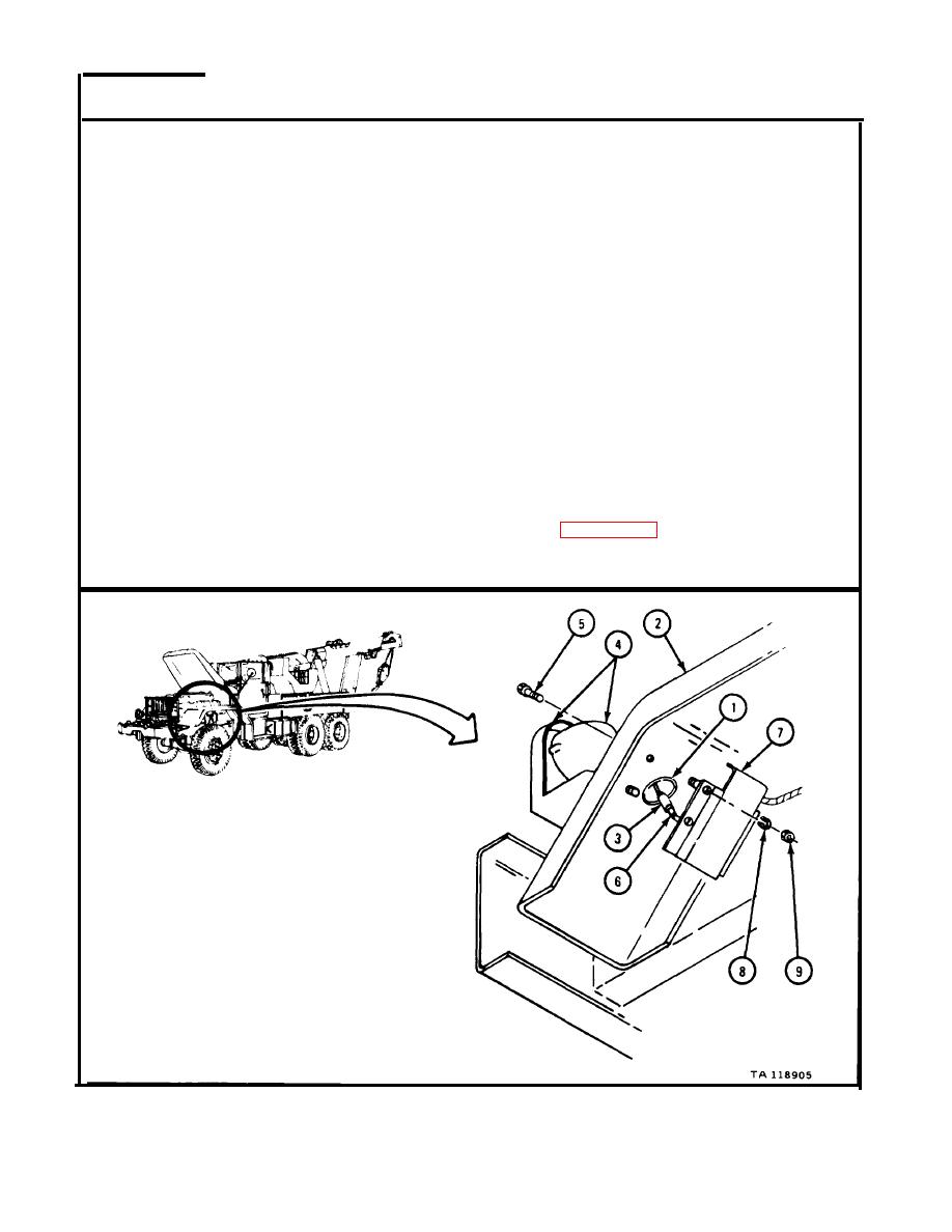
P u t grommet (1) in place on fender (2).
2.
P u t electrical lead connector (3) through grommet (1) , and put emergency light
a n d bracket (4) in place, alining holes.
3.
P u t in four screws (5).
4.
W o r k i n g under fender, push electrical lead (6) into electrical lead connector
(3).
5.
Put protector box (7) and four lockwashers (8) in place on screws (5). Screw
o n and tighten four nuts (9).
NOTE
Follow-on Maintenance Action Required:
1.
R e p l a c e shielded blackout headlight assembly and
g r o u n d s t r a p . R e f e r to TM 9-2320-211-20.
2.
R e p l a c e b r u s h g u a r d . R e f e r to TM 9-2320-211-20.
3.
R e p l a c e headlight assembly. Refer to
T M 9-2320-211-20.
4.
R e c o n n e c t battery ground cable. Refer to
T M 9-2320-211-20.
5.
R e p l a c e hood side panel. Refer to para 16-3.
6.
C l o s e h o o d . R e f e r to TM 9-2320-211-10.
END OF TASK
16-118
|
|
Privacy Statement - Press Release - Copyright Information. - Contact Us |