 |
|||
|
|
|||
|
Page Title:
Launch Equipment Re-Fitting-continued |
|
||
| ||||||||||
|
|
 TM 5-5420-279-23
(20)
Insert A-Frame rotate shoot bolts.
(21)
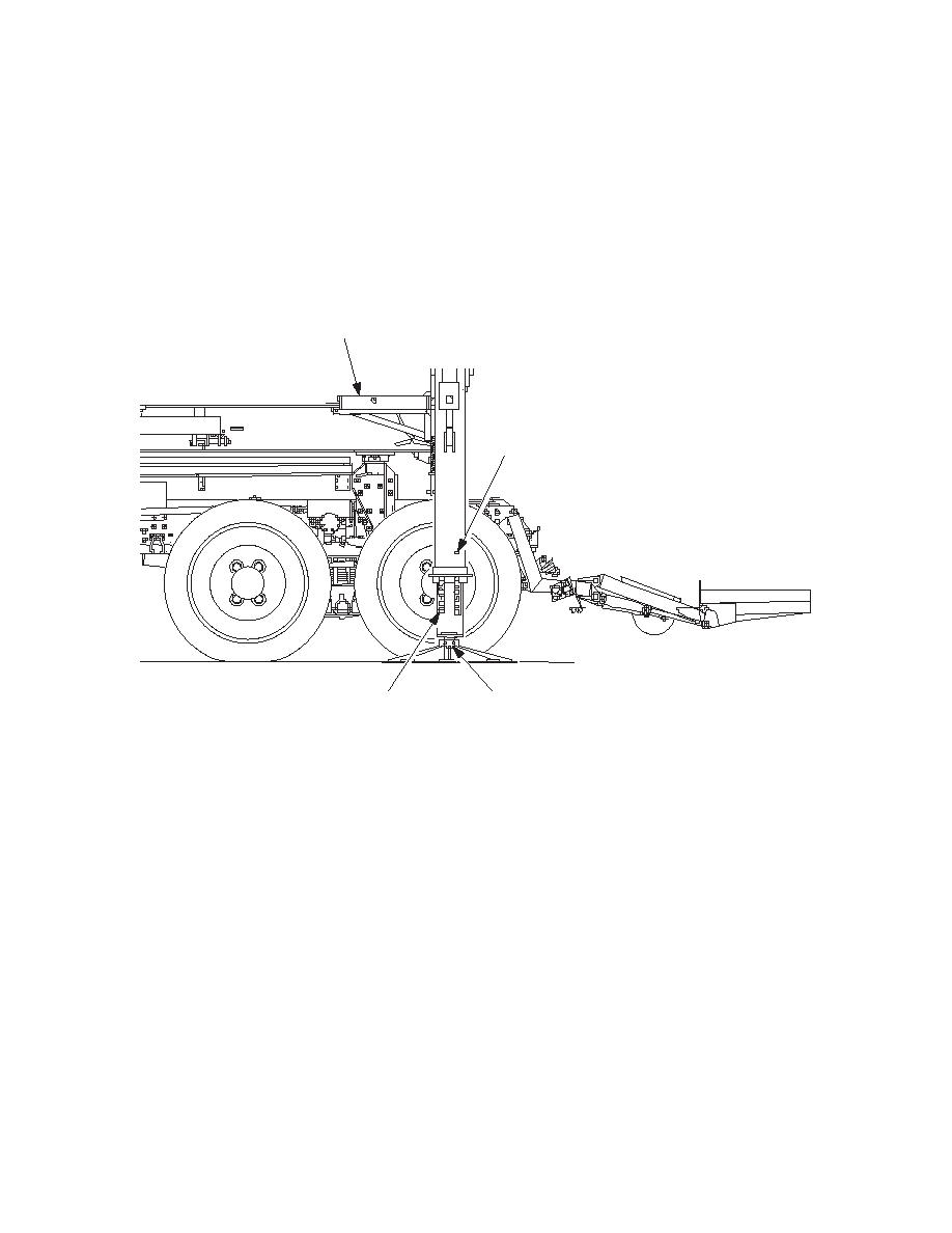
Position stabiliser feet under stabiliser legs.
(22)
Remove stabiliser leg pins and r clips.
(23)
Lower stabiliser legs onto the feet.
NOTE
Only just rest the feet on the ground DO NOT start to lift the A-Frame.
(24)
Refit stabiliser feet by fitting the securing u-bolt and new nyloc nuts.
1, 6
22, 32, 33
23
21, 22, 24
686A662
(25)
Release twist locks on both sides, raise stabiliser legs to pin hole number eleven, replace
pins and clips.
(26)
Drive vehicle forward to extend launch frame.
(27)
Plug launcher chest pack controller in, remove shoot bolts on relax mechanism.
(28)
Go to position four on four position rotary switch in the vehicle cab.
(29)
Go to beam angle on the chest pack. Operate the right hand joystick to exercise articulator
cylinders up and down to check for correct operation.
(30)
Insert shoot bolts on relax mechanism, unplug launcher chest pack controller.
(31)
Turn rotary switch to position three reverse vehicle to close slide frame.
(32)
Remove pin and clip from a- frame stabiliser leg.
(33)
Retract stabiliser legs replace pins and r clips.
(34)
Rotate twist lock handles to the lock position.
(35)
Remove shoot bolts where the mudguards are fitted to the A-Frame.
(36)
Rotate the A-Frame legs. Press A-Frame rotate park button on the interface panel until the
parked light comes on.
(37)
Remove the two A-Frame hinge locking pins from each side.
5-485
|
|
Privacy Statement - Press Release - Copyright Information. - Contact Us |