 |
|||
|
|
|||
|
Page Title:
SLIDE FRAME - TWIST LOCK ASSEMBLY |
|
||
| ||||||||||
|
|
 TM 5-5420-279-23
This task covers:
a. Remove
b. Install
INITIAL SETUP:
Tools Required
Personnel Required
Tool Kit, General Mechanic's,
Two
Automotive (GMTK)
Equipment Conditions
Materials Required
A-Frame deployed
Slide Frame deployed
Nyloc nuts (Qty 14)
NOTE
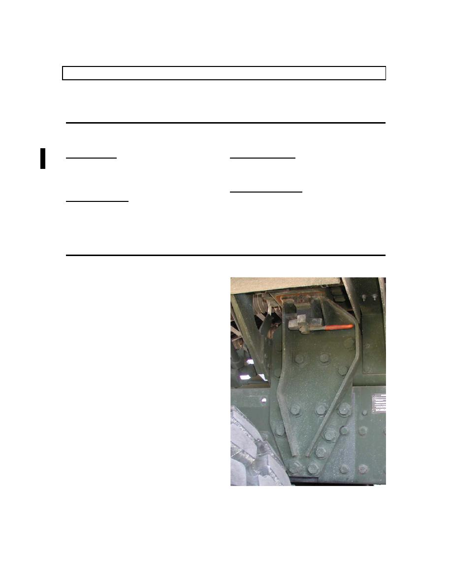
The slide frame lower twist lock assemblies
are mounted on the left and right sides of
the vehicle chassis between the two rear
axles.
If required, the twist lock assembly and
mounting bracket can be removed as a
complete assembly; by removing the
fourteen bolts, eighteen washers and
fourteen nyloc nuts securing the bracket to
the vehicle chassis.
|
|
Privacy Statement - Press Release - Copyright Information. - Contact Us |