 |
|||
|
|
|||
|
|
|||
| ||||||||||
|
|
 TM 5-5420-279-23
b.
Install
(1)
Position the articulator cylinder (1) on
the bottom mounting on the cross
member assembly (4).
(2)
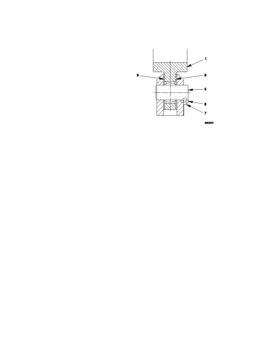
Place the spacers (9) in between the
mounting and the articulator cylinder
(1).
(3)
Fit the cylinder pin (5) through the
articulator cylinder (1), spacer (9) and
mounting.
(4)
Fit the locking plate (7) and secure in
place with the two screws (6).
(5)
Position the articulator cylinder (1) on
the top mounting on the launch beam
drive assembly (2).
(6)
Place the spacers (9) in between the mounting and the articulator cylinder (1).
(7)
Fit the cylinder pin (5) through the articulator cylinder (1), spacer (9) and mounting.
(8)
Fit the locking plate (7) and secure in place with the two screws (6).
(9)
Position the stow cylinder (3) on the middle mounting on the articulator cylinder (1).
NOTE
It may be necessary to release the bleed fitting on the cylinder to allow the cylinder piston
to be moved. Always tighten the bleed fitting when the cylinder has been fitted.
(10)
Place the spacers (9) in between the mounting and the stow cylinder (3).
(11)
Fit the cylinder pin (5) through the stow cylinder (3), spacer (9) and mounting.
(12)
Fit the locking plate (7) and secure in place with the two screws (6).
(13)
Fit the hydraulic hoses (8) to the articulator cylinder (1) in the positions noted during
removal.
(14)
Remove the lifting devices and slings.
(15)
Operate the articulator cylinder in accordance with the operator's manual TM 5-5420-279-
10.
(16)
Check for hydraulic oil leaks.
(17)
Replace the first section of the fixed walkway refer to unit maintenance procedure 5-090.
5-185
|
|
Privacy Statement - Press Release - Copyright Information. - Contact Us |