 |
|||
|
|
|||
|
Page Title:
TSUM - 3-008 A-Frame Lower (91) Part 2 |
|
||
| ||||||||||
|
|
 TM 5-5420-279-23
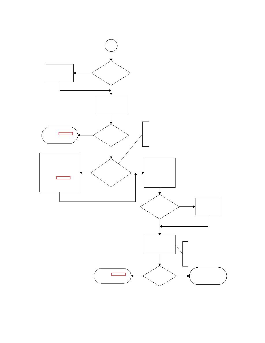
TSUM - 3-008 A-Frame Lower (91) Part 2
Part 2
Replace
Is
No
defective solenoid.
solenoid SV3
See maintenence
resistance between
15-23Ω ?
procedure 5-124
Yes
Manually operate SV3
and move joystick
backward to lower
A-Frame
NOTE
The LED for valve PV1a on
Hydraulic fault on valve
the Mimic Panel will glow
Does
Yes
SV3. See chapter 2
with varying intensity,
A-Frame
hydraulic trouble shooting
dependent on the
lower?
procedure 2-011
displacement of the Chest
Pack RH Joystick
No
Power down & check harness
continuity from solenoid PV1b
Disconnect connector
on the Launch Fram e W inch
from solenoid PV1a.
Is
Control Manifold to the Launch
See maint procedure
PV1a LED Lit on
No
Yes
Frame Enclosure using the
5-141. Connect DMM
Mimic Panel when RH
cable routing tables in section
across solenoid coil
Joystick moved
3.6 of Chapter 3.
pins. See resistance
backward?
Replace faulty harness as
check in maint
appropriate. See maintenance
procedure 5-124
procedure 5-139
Is
Replace
solenoid PV1a
defective solenoid.
resistance between
See maintenance
No
3-8Ω ?
procedure 5-124
Yes
Manually operate
backup mode m otion
NOTE
valve to lower
The backup m ode
A-Frame
motion valve is located
on the A-Frame RH
Stabiliser Leg. Refer to
-10 Chapter 7 of
Operator Manual
Hydraulic fault on valve
Does
Mechanical fault, refer to
PV1. See chapter 2
A-Frame
-10. Chapter 9 of operator's
hydraulic trouble shooting
No
Yes
lower?
manual.
procedure 2-011
|
|
Privacy Statement - Press Release - Copyright Information. - Contact Us |