 |
|||
|
|
|||
|
Page Title:
TSUM - 3-002 A-Frame Rotate (Deploy) (17) Part 1 |
|
||
| ||||||||||
|
|
 TM 5-5420-279-23
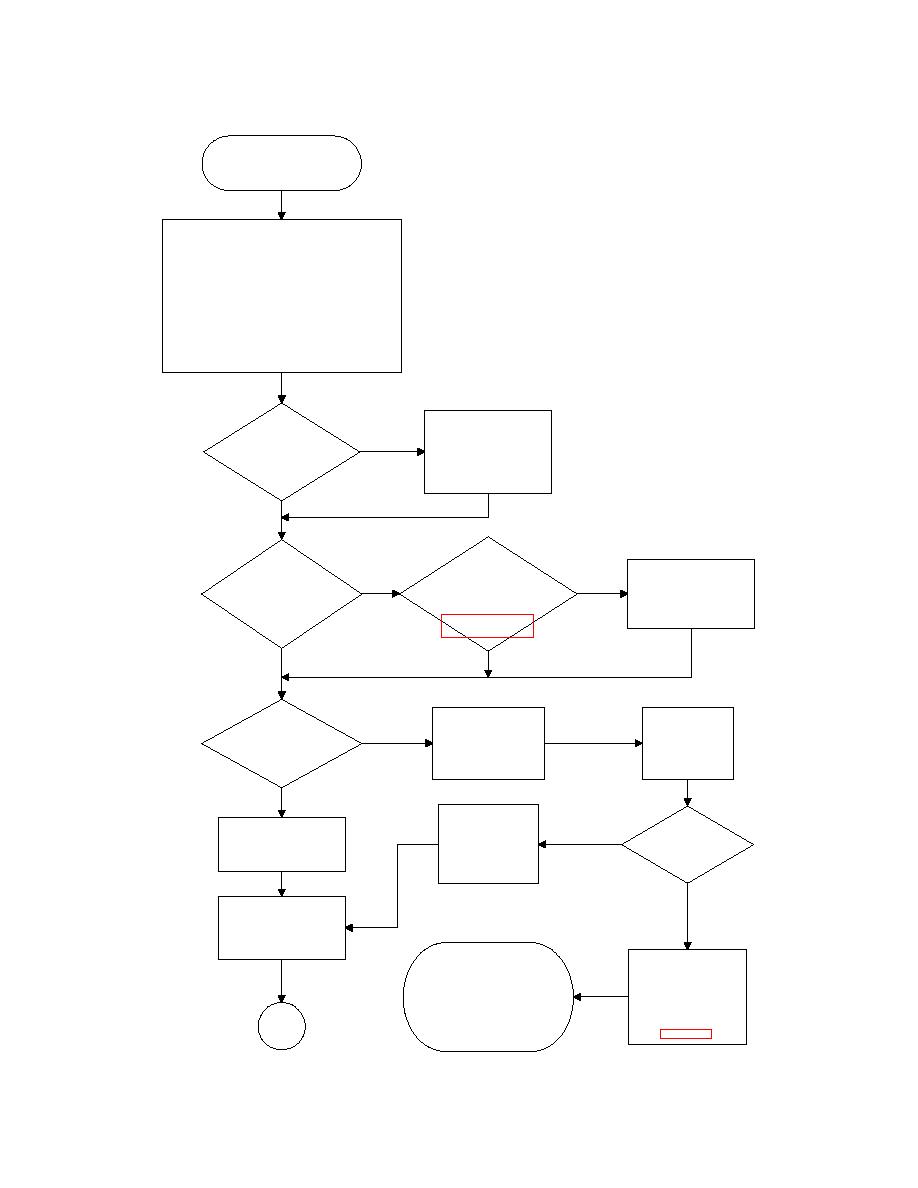
A-Fram e does not rotate when
A-Fram e Rotate Deploy button on
Operator Panel is pressed.
For the A-Fram e to rotate to the deployed position
the following conditions m ust be satisfied:-
* Neutral gear selected
* Parking brake applied
* Tail Lift Pendant connected & powered
* Chest Pack not connected
* 4 Position Switch at position 2
* A-Fram e unfolded (open)
* Launcher Down signal from Launcher Down Lim it
Switch
* A-Fram e Rotate Deploy button depressed
Power down & replace
defective Interface
Perform
No
Enclosure. To replace
lam p test on
Interface Enclosure see
Operator Panel. Are all
m aintenance procedure
lam ps lit?
5-098
Yes
Are
Is
Lim it Switches
Launcher
Adjust / replace Lim it
LS2 & LS4 functioning
No
No
Deploym ent lam p and
Switch(es) as appropriate.
correctly? See wiring diagram
Solenoid SV19b lam p lit on
See m aintenance
G406-8604 Sheet 5 at
Operator
procedure 5-023
Panel?
Yes
Yes
Is
Disconnect connector
Insert probes of
solenoid SV19b
No
from solenoid SV19b.
DMM into sockets
connector LED lit on the
See m aint procedure
1 & 2 of
A-Fram e Rotate
5-141
connector
Manifold?
Yes
Replace solenoid
Disconnect connector
Is 24V
harness if connector
from solenoid SV19b.
solenoid supply
LED not lit. See
See m aint procedure
Yes
present?
m aintenance
5-141
procedure 5-139
No
Connect DMM across
solenoid coil pins.
See resistance check in
m aint procedure 5-124
Replace faulty harness,
Power down & check
interface enclosure or junction
harness continuity from
box as appropriate using the
solenoid SV19b to
following m aintenance procedures:-
Interface Enclosure
Harness 5-139
using the cable routing
Go to
Interface Enclosure 5-098
tables in section 3.6 of
Part 2
Slide Fram e Junct. Box 5-089
Chapter 3
|
|
Privacy Statement - Press Release - Copyright Information. - Contact Us |