 |
|||
|
|
|||
|
Page Title:
Section III. REPAIR AND REPLACEMENT |
|
||
| ||||||||||
|
|
 TM 11-6625-601-34
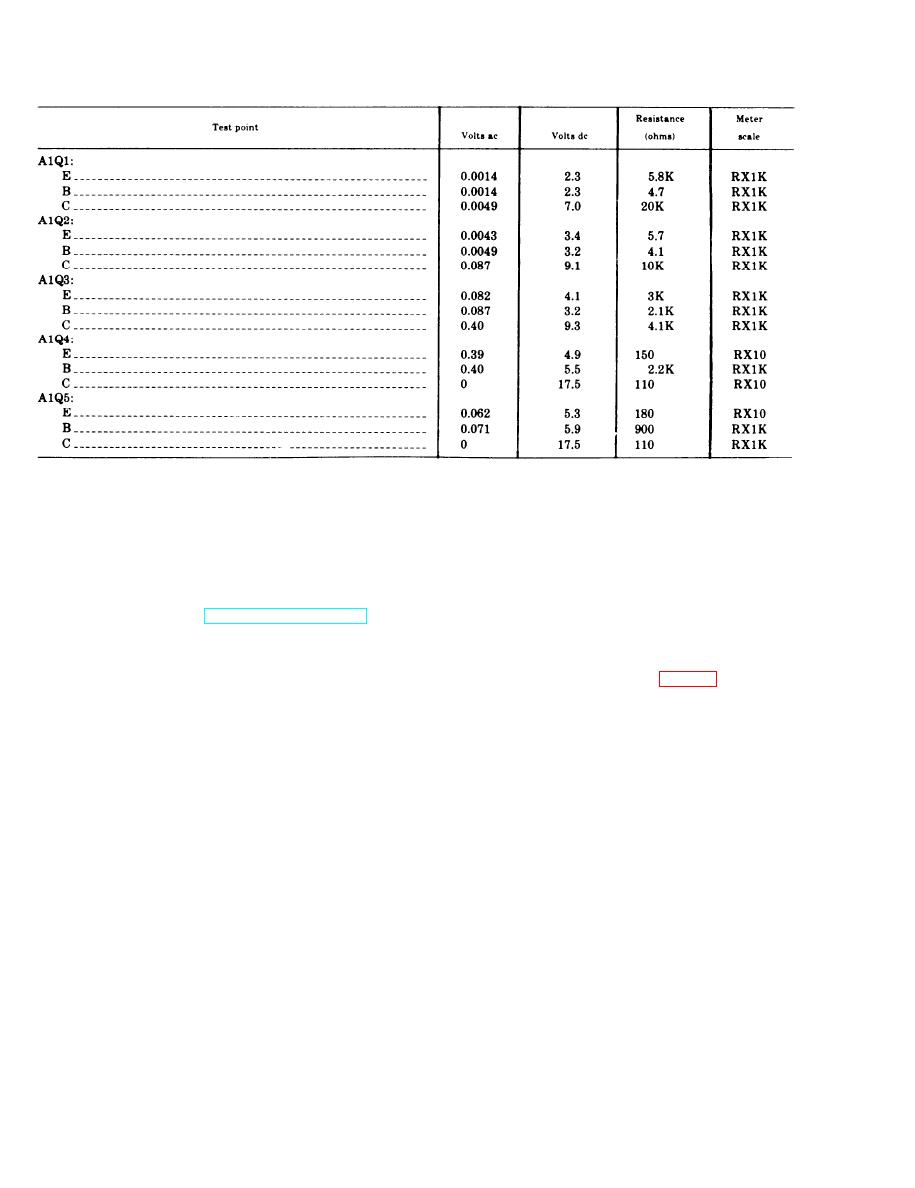
Table 2-3. Voltage and Resistance Measurements for Audio Amplifier A1 (Part of SM-349/ARC-54)
Section Ill. REPAIR AND REPLACEMENT
mits, use a heat sink (such as long-nosed pliers)
2-6. General Instructions
between the soldered joint and the transistor.
The direct support maintenance procedures
Use approximately the same length and dress
given in this manual supplement the procedures
of transistor leads as used originally.
described in the operator and organizational
maintenance manual (TM 11-6625-601-12). The
2-8. Removal and Replacement of Audio
systematic troubleshooting procedure, which
Amplifier A1 (Located in TS-1967/
begins with the operational and sectionalization
ARC-54)
checks that can be performed at an organiza-
tional level, is carried to a higher level in this
lows:
manual.
(1) Remove the six screws, lockwashers,
and nuts (4) that secure the attenuator plate
2-7. General Parts Replacement Techniques
(5) to the test set chassis.
a. Most of the test set and simulator parts are
(2) Remove the attenuator plate (5) from
readily accessible and can be replaced easily
the test set chassis; be careful not to put too
without special procedures. To gain access to
much strain on the wire harness (6).
the interior of the test set, remove 10 screws
(3) Remove the four screws and flat
from around the edges of the front panel and
washers (1) that secure the audio amplifier
lift it from the lower case; use the two handles.
board (2) to the test set chassis.
To gain access to the interior of the simulator,
(4) Pull the audio amplifier board (2) away
remove the eight screws that secure the metal
from the chassis until the wires connected to
cover to the simulator chassis. Carefully lift the
the terminals on the bottom are accessible.
metal cover from the simulator.
(5) Tag and unsolder all wires that connect
b. Use a pencil-type iron with a 25-watt max-
the audio amplifier board (2) to the cable har-
imum capacity when replacing components con-
ness (3).
tained in transistorized circuits. If the iron
(6) Remove the audio amplifier board (2).
must be used with ac, use an isolating trans-
b. Replace audio amplifier A1 as follows:
former between the iron and the line. Do n o t
(1) Connect and solder each wire to its
use a soldering gun; damaging voltages can be
r e s p e c t i v e terminal on the audio amplifier
induced in components. When soldering transis-
board (2).
tor leads, solder quickly; whenever wiring per-
(2) Position the audio amplifier board (2) in
2-12
|
|
Privacy Statement - Press Release - Copyright Information. - Contact Us |