 |
|||
|
|
|||
|
Page Title:
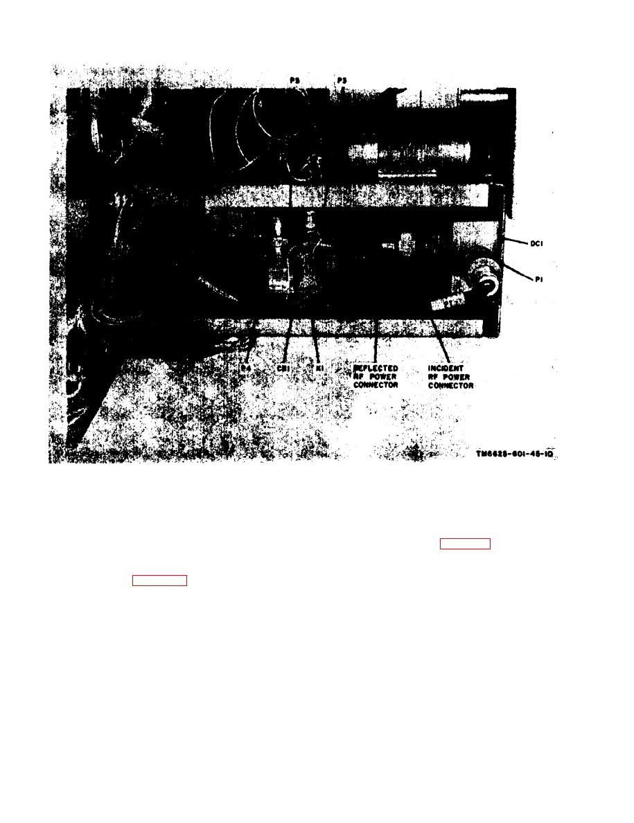
Figure 2-2. Test Set, Radio TS-1967/ARC-54, inside left view, parts location. |
|
||
| ||||||||||
|
|
 TM 11-6625-601-34
Figure 2-2. Test Set, Radio TS-1967/ARC-54, inside left
view, parts location.
b. Resistance Measurements. The resistance
(h) Connect the vtvm between the test set
AUDIO OUT terminals. Note 390 mv rms is
readings in the tables (para 2-5) were obtained
indicated on the vtvm. If this reading is not
under the conditions outlined in (1) through (4)
obtained, perform the audio amplifier adjust-
below. Always make resistance measurements
under these conditions, or the readings may be
ment procedure (para 2-21).
inaccurate.
CAUTION
(1) Make all resistance measurements with
Multimeter TS-352/U, or equivalent. The open-
Before using any ohmmeter. to make
circuit voltage across the ohmmeter test leads
r e s i s t a n c e measurements, check the
must not exceed 1.5 volts.
open-circuit voltage across the ohmme-
(2) For each resistance measurement, set
ter test leads. Do not use the ohmmeter
the ohmmeter range switch to the resistance
if the open-circuit voltage, exceeds 1.5
scale specified in the table.
volts. Make resistance measurements
(3) Connect the ohmmeter negative lead to
in the test set and simulator only as
chassis ground of the unit under test unless
directed in the tables below. Sensitive
otherwise indicated.
transistors can be ruined if unauth-
(4) Make all resistance measurements with-
o r i z e d resistance measurements are
out power applied to the test set and simulator.
made.
2-4
|
|
Privacy Statement - Press Release - Copyright Information. - Contact Us |