 |
|||
|
|
|||
|
Page Title:
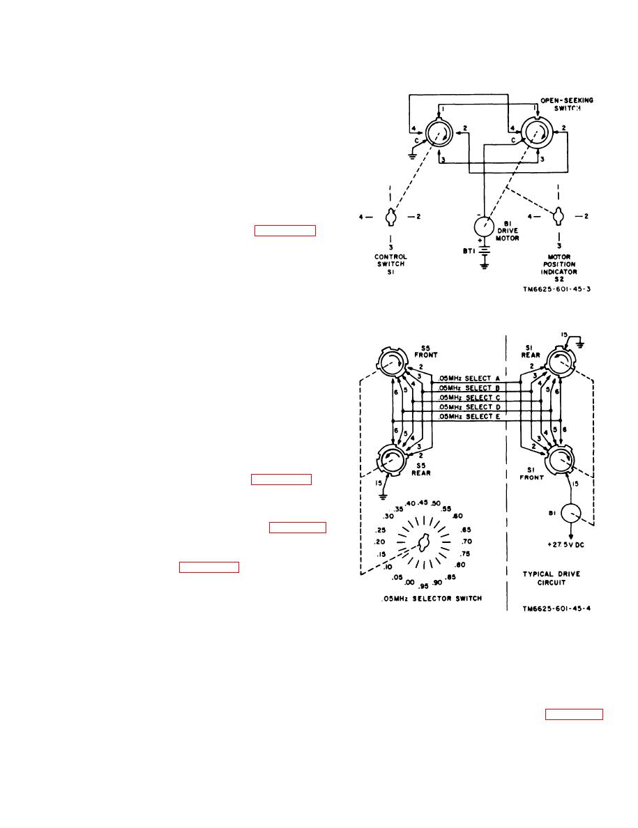
Figure 1-3. Simplified four-wire reentrant switch and drive motor circuit |
|
||
| ||||||||||
|
|
 TM 11-6625-601-34
for the 30- and 50-megahertz ranges, and
switches S4A and S4C generate the code for the
40- and 60-megahertz ranges. To distinguish
between frequencies that have the same code
(that is, 35 and 55 megahertz), switch S3A
(front) generates an ambiguity code. Odd- and
even-megahertz frequencies are identified by a
coded ground obtained from switch S4E (front).
Switch S4E (front) routes a ground from trans-
mit control switch S6 (XMIT or PTT position)
through switch S3D (front) at frequencies below
46 megahertz to operate the harmonic filter in
the RT-348/ARC-54.
a simplified schematic diagram of a simple open-
seeking reentrant system. With the switches in
the positions shown, ground is applied through
contacts C and 1 of switch S1 to contact 1 of
switch S2. Because contact 1 of switch S2 is at
the open segment of switch S2, the motor circuit
is open. Setting switch S1 to 2 applies ground,
Figure 1-3. Simplified four-wire reentrant switch and drive
motor circuit.
through contacts C and 2 of switch S1, contact
2 of switch S2, and contact C of switch S2, to
motor B1. Motor B1 operates, turning switch S2
clockwise. When the open segment of switch S2
reaches contact 2, the circuit opens and motor
B1 stops. The action described above is the same
for any position of switch S1; switch S2 always
stops motor B1 at the position selected by
switch S1. Note that switches S1 and S2 are
physically complementary; this is a characteris-
tic of all reentrant systems. The switching
arrangement of the test set frequency selector
system, shown schematically in figure 1-2, is
more complex than the system discussed above.
However, the test set switches provide a basic
function similar to that of switch S1 shown in
the simple switching arrangement of figure 1-3.
c. Simplified
0.05-Megahertz
Switching.
Switch S5 selects fraction megahertz in steps
of 0.05 megahertz. Figure 1-4 shows the 0.05-
megahertz selector switch connected to a typi-
cal drive circuit. Switch S5 is shown in the .00
position. In this position, 0.05-megahertz select
lines A and E are grounded by switch S5 (rear).
Drive motor B1 has positioned switch S1 so that
Figure 1-4. Simplified .05 megahertz selector switch and
typical drive circuit.
0.05-megahertz select lines A and E, connected
to contacts 2 and 6 of switch S1 (front), respec-
is broken, which stops motor B1. The same
tively, are open. Setting switch S5 to .05 applies
action described above occurs for other posi-
g r o u n d through switch S5 (rear) to 0.05-
tions of switch S5. The table in d below gives
megahertz select line B. Ground from 0.05-
the coding of 0.05-megahertz selector switch S5.
megahertz select line B, applied through con-
tact 3 of switch S1 (front), energizes motor B1;
b e l o w shows the ground coding of 0.05-
this turns switch S1 in the direction shown by
m e g a h e r t z switch S5. An X in the column
the arrows. When contact 3 reaches the open
segment of switch S1 (front), the ground circuit
indicates ground: a O indicates an open.
1-11
|
|
Privacy Statement - Press Release - Copyright Information. - Contact Us |