 |
|||
|
|
|||
|
Page Title:
Frequency Selection Circuit |
|
||
| ||||||||||
|
|
 TM 11-6625-601-34
of transformer T1 drops to zero when the core
ferent conduction characteristics of the two
saturates, causing the collector current of Q1
transistors cause one to conduct more heavily
to decrease. The magnetic field around the win-
than the other. Assuming higher conduction in
transistor Q1, c u r r e n t flows from ground,
dings of transformer T1 collapses as the collec-
through switch S6 (XMIT or PTT position),
tor current of transistor Q1 decreases, inducing
voltage of opposite polarity in the windings. The
transistor Q1, and winding 4-3 of transformer
opposite polarity cuts off transistor Q1 and
T1, to the +27.5-volt dc supply. This current flow
turns on transistor Q2. The collector current of
induces a voltage in winding 4-5 of transformer
transistor Q2 flows through winding 2-3 of
T1, which is negative at terminal 5. The nega-
transformer T1 until the core saturates. The
tive voltage at terminal 5 drives the base of
sequence is repeated as the field collapses and
transistor Q1 negative, increasing the collector
current. The voltage induced in winding 21 of
the voltage changes polarity, resulting in a 54-
volt, 800-Hz square-wave output symmetrical
transformer T1 is positive at terminal 1. This
w i t h respect to ground. The output taken
voltage drives the base of Q2 positive, decreas-
between the emitter of transistors Q1 and Q2
ing the collector current. This action continues
is applied direct to the blower motor. When
until the collector current of transistor Q1 flow-
ing through terminals 4-3 saturates the trans-
switch S6 is in the RCV position, ground is
former core. The voltage induced in winding 4-5
supplied from the RT-348/ARC-54.
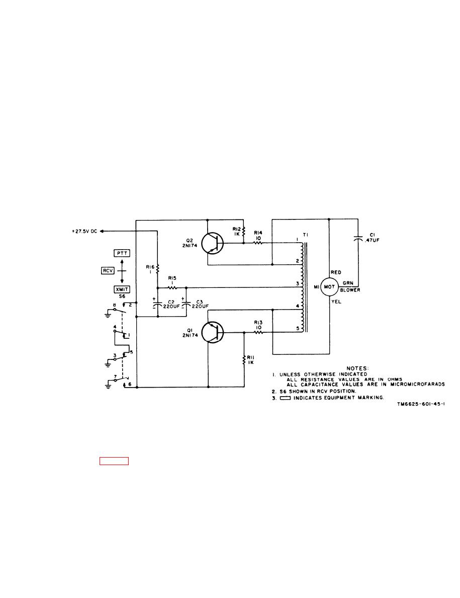
Figure 1-1. Blower and inverter, simplified schematic
diagram.
1-10. Frequency Selection Circuit
frequency, and switch S5 selects increments of
0.05 megahertz. Switch S5 applies a different
a. General. The RT-348/ARC-54 tuning sys-
ground sequence for each of 20 switch positions,
tem is composed of three five-wire reentrant
to the 0.05-megahertz select lines. Switch S4
systems, one for 0.05-megahertz tuning and two
generates two separate coded sequences corres-
f o r whole-megahertz tuning. FREQUENCY
ponding to the whole-megahertz frequencies
SELECTOR-MC switches S3, S4, and S5 in the
from 30 to 69 megahertz. Coding for the 30- to
test set generate codes that tune the
39- and 40- to 49-megahertz frequency ranges
RT-348/ARC-54 to any desired frequency from
is identical with the coding of the 50- to 59- and
30.00 to 69.95 megahertz in steps of 0.05 MHz.
60- to 69-megahertz frequency ranges, respec-
Switches S3 and S4 select the whole-megahertz
tively. Switches S4B and S4D generate the code
1-9
|
|
Privacy Statement - Press Release - Copyright Information. - Contact Us |