 |
|||
|
|
|||
|
Page Title:
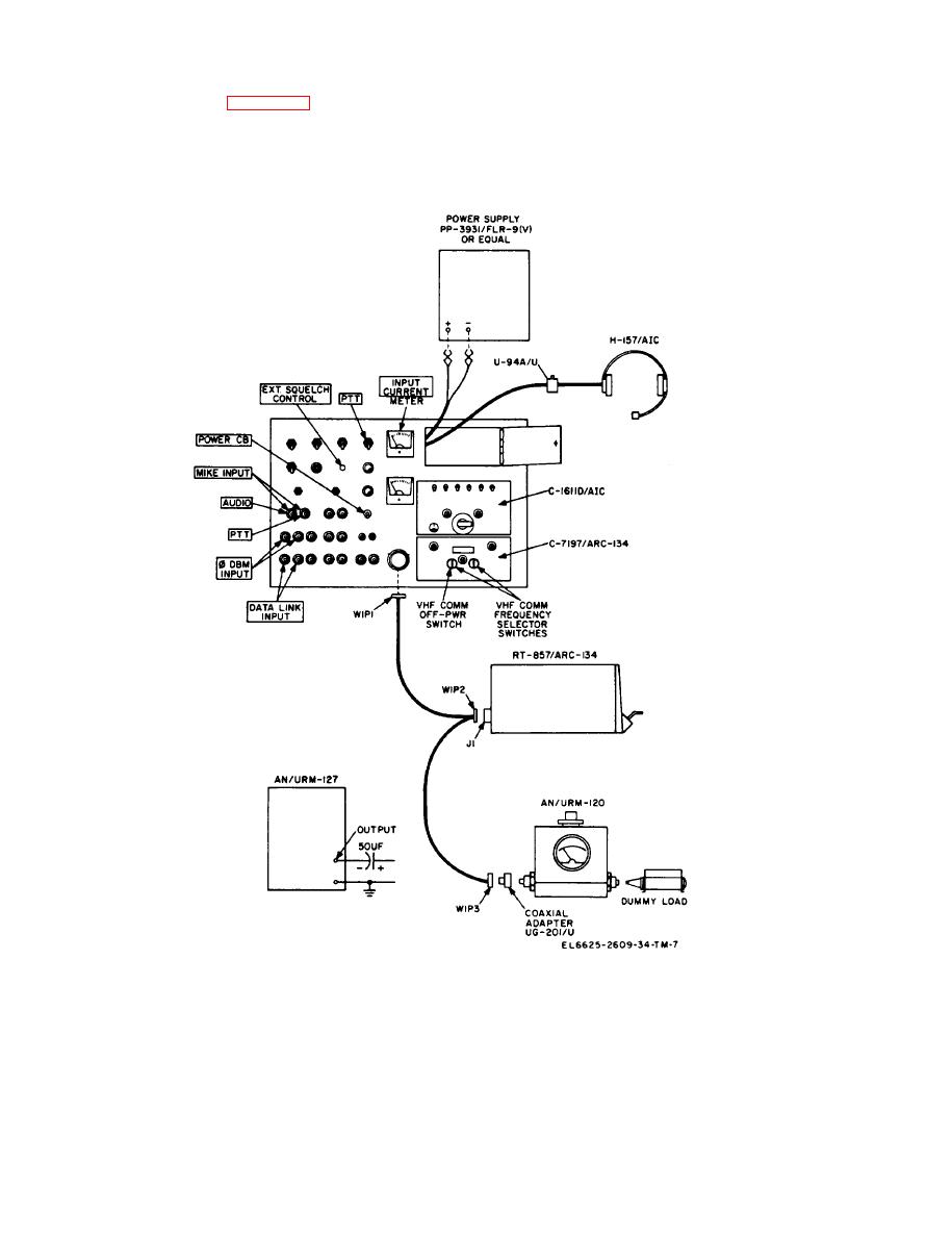
Figure 3-6. Transmitter circuit test setup. |
|
||
| ||||||||||
|
|
 TM 11-6625-2609-34
equipment as shown in figure 3-6. The AN/URM
RECEIVERS switches off, and position the VOL
127 is not used in this test. Place the C-1611D/
control as required. These settings must be main-
AIC transmit-interphone selector switch in posi-
tained during the test.
tion 3, the RECEIVERS 3 switch ON, all other
Figure 3-6. Transmitter circuit test setup.
c. Procedure.
Control settings
steps
Test equiptment
Equiptment under test
Test procedure
Performance standard
AN/ARC-134
1
Set all test panel switches a. Apply primary oper-
a. None.
Set meter switch tO
to OFF and set EXT.
sting power to test
LINE V.
SQUELCH CONTROL
equipment and main-
AN/URM-120
fully counterclockwise.
tenance kit.
Set above 26.
3-14
|
|
Privacy Statement - Press Release - Copyright Information. - Contact Us |