 |
|||
|
|
|||
|
Page Title:
Section IV. MAINTENANCE OF MK-1004A/ARC |
|
||
| ||||||||||
|
|
 TM 11-6625-2609-34
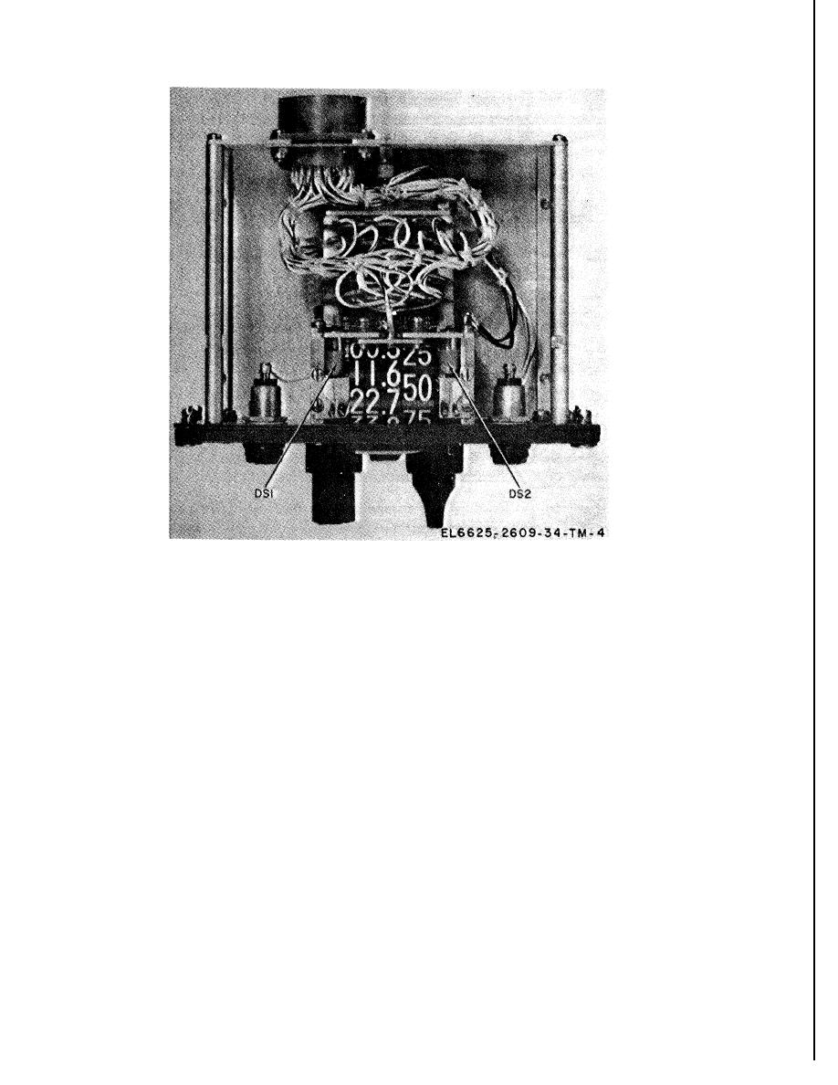
Figure 3-3. Radio control, to cover removed, top view.
Figure 3-4. Test panel, schematic diagram.
(Located in back of manual)
Section IV.
M A I N T E N A N C E OF MK-1004A/ARC
ing that is to be disconnected. Make a note of
3-5. General Parts Replacement Techniques
color coding, placement of wires, and method of
Except for the radio control and intercom control,
insulation before unsoldering wires.
the parts of the maintenance kit can be easily
reached and replaced without special procedures.
b. Use a pencil-type soldering iron with a 25-
Disassembly and reassembly of Radio Set Control
watt maximum capacity. If the iron must be used
C-7197/ARC are covered in TM 11-5821-277-35
with an alternating current (ac) source, use an
and Intercommunication Control Set C1611D/
isolating transformer between the iron and the
AIC is covered in TM 11-5831201-20 or TM
line.
11583120135. Several parts replacement tech-
niques are presented below.
and use a heat sink (such as long-nose pliers)
a. Before a part is removed, note the position
of the part and tag or otherwise identify all wir-
between the soldered joint and the diode.
Section V. DIRECT SUPPORT TESTING PROCEDURES
3-6. General
electronics equipment to determine the accepta-
a. Testing procedures are prepared for use by
bility of repaired electronics equipment. These
maintenance shops and service organizations re-
procedures set forth specific requirements that
sponsible for DS (direct support) maintenance of
repaired electronics equipment must meet before
3-8
|
|
Privacy Statement - Press Release - Copyright Information. - Contact Us |