 |
|||
|
|
|||
|
|
|||
| ||||||||||
|
|
 TM 11-6625-2609-12
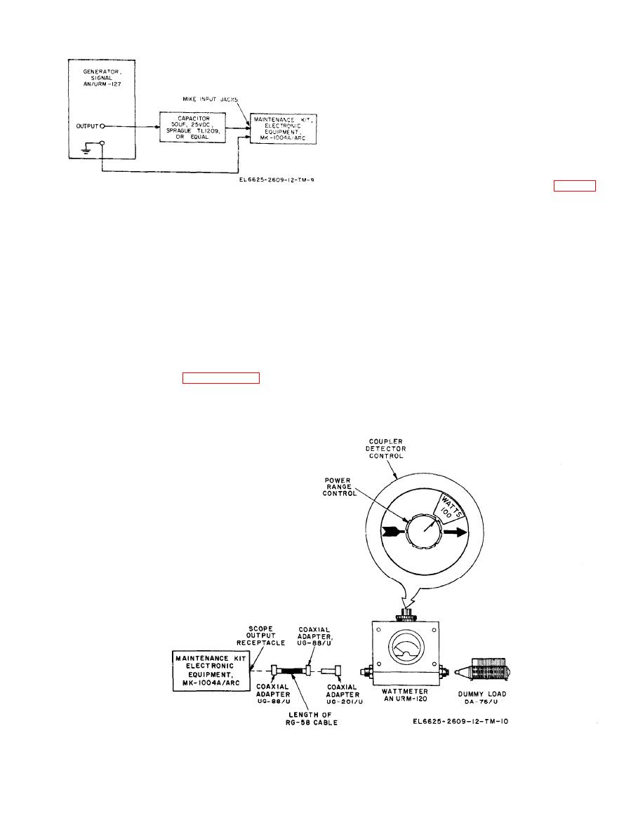
50-microfarad blocking capacitor to the test
panel MIKE INPUT jacks.
( 2 ) Connect the ME-30A/U to the test
panel DETECTOR METER jacks. Set the ME-
30A/U to the 10-volt range.
(3) Disconnect antenna connector W1P3 on
the maintenance kit from the AN/URM-120, and
connect W1P3 to the test panel DET INPUT re-
ceptacle.
(4) Connect the AN/URM-120 (fig. 2-6)
to the test panel SCOPE OUTPUT receptacle.
to maintenance kit.
(5) Set the test panel PTT switch to ON
and increase the AN/URM-127 output level. Mod-
(6) Set the test panel PTT switch to ON
ulation should be indicated by a meter deflection
and increase the AN/URM-127 output level. A
on the ME-30A/U.
modulation indication should be observed on the
(6) Set PTT switch to OFF.
AN/ARC-134.
(7) Repeat the procedure given in (5) and
a. To remove operating power from the AN/
(6) above with the AN/URM-127 connected first
ARC-134, set the VHF COMM OFF-PWR
to the test panel DBM INPUT jacks and then
switch to OFF. The indicator lamps behind the
to the DATA LINK INPUT jacks.
VHF COMM frequency counter dials should go
(8) Set PTT switch to OFF.
out.
h. Detector Circuit Checks. Start the equip-
b. To remove all power from the maintenance
ment as instructed in paragraph 2-6 and pro-
kit, set the test panel POWER CB circuit breaker
ceed as follows:
to OFF. The test panel 28.7 VDC indicator lamp
(1) Reconnect the AN/URM-127 through a
should go out.
connected to maintenance kit detector.
|
|
Privacy Statement - Press Release - Copyright Information. - Contact Us |