 |
|||
|
|
|||
|
Page Title:
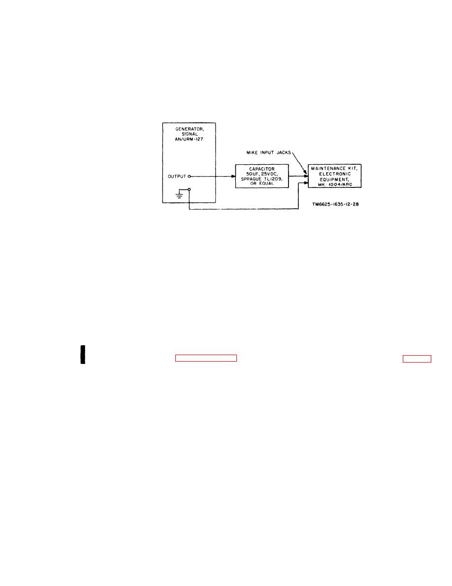
Figure 2-6. Signal Generator AN/URM-127, connected to maintenance kit. |
|
||
| ||||||||||
|
|
 TM 11-6625-1635-12
C1
Figure 2-6. Signal Generator AN/URM-127, connected to maintenance kit.
AN/URM-127
(6) Set the AN/URM-127 to a frequency
the
(1) Reconnect
of 1,000 Hz.
through a 50-f blocking capacitor to the test
(7) Set the test panel PTT switch to ON
p a n e l MIKE INPUT jacks.
and increase the AN/URM-127 output level. A
( 2 ) Connect the TS-352B/U to the test
modulation indication should be observed on the
panel DETECTOR METER jacks. Set the TS-
AN/ARC-134.
352B/U to the 10-volt range on the OUTPUT
(8) Repeat the procedure given in (5), (6),
scale.
( 3 ) Disconnect antenna connector J 1 on
and (7) above with the AN/URM-127 con-
the maintenance kit from the A N / U R M - 4 3 A ,
nected first to the test panel D B M I N P U T
jacks and then to the data link input jacks.
and connect J1 to the test panel DETECTOR
i. Detector Circuit Checks. Start the equip-
I N P U T receptacle.
m e n t a s i n s t r u c t e d in p a r a g r a p h 2 - 5 a n d
(4) Connect the AN/URM-43A (fig. 2-7)
proceed as follows:
to the test panel SCOPE OUTPUT receptacle.
2-11
|
|
Privacy Statement - Press Release - Copyright Information. - Contact Us |