 |
|||
|
|
|||
|
|
|||
| ||||||||||
|
|
 T M 9-2815-210-34-2-2
c. R e p a i r . Repair minor damage to fuel pump by filing burrs and threads of
receptacle connector.
d.
R e l i e f Valve Adjustment.
WARNING
Smoking, sparks or open flames are not allowed
w i t h i n 50 feet of work area during this task.
F i r e or explosion could occur, causing injury
t o personnel and damage to equipment.
NOTE
This is an alternate procedure given for refer-
e n c e p u r p o s e s o n l y . S t a n d a r d procedure is to
a d j u s t relief valve during dynamometer test and
adjustment.
FRAME 1
CAUTION
Flame heater fuel pump electrical system is negative
g r o u n d e d . P i n A is positive and pin B is negative. Do
n o t switch polarity of pump during checking or replace-
m e n t . Changing polarity will permanently damage pump.
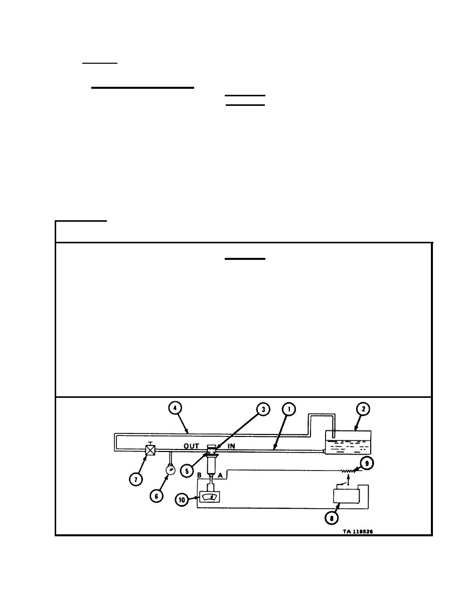
Hook up h o s e (1) from supply tank (2) of diesel fuel to pump inlet ( 3 ) .
1.
Hook up r e t u r n hose (4) from fuel pump outlet (5) back to supply tank (2).
2.
3.
R e t u r n hose must have 200 psi pressure gage (6) and adjustable valve (7) put
o n as shown.
Hook up 24-volt battery (8) with rheostat (9) to fuel pump receptacle.
4.
H o o k up voltmeter (10) to fuel pump.
5.
GO TO FRAME 2
|
|
Privacy Statement - Press Release - Copyright Information. - Contact Us |
