 |
|||
|
|
|||
|
|
|||
| ||||||||||
|
|
 TM 9-2815-210-34-2-2
FRAME
3
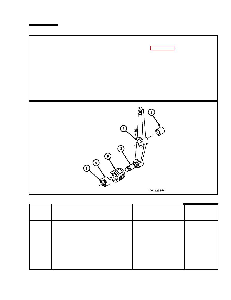
NOTE
R e a d i n g s must be within limits given in table 4-64. If
r e a d i n g s are not within given limits, throw away part
and get a new one.
Measure a r m assembly bore (1).
1.
Measure d i a m e t e r of fan idler shaft (2).
2.
Measure s l e e v e b u s h i n g o u t s i d e d i a m e t e r ( 3 ) .
3.
Measure b e a r i n g outside diameter (4) and inside diameter (5).
4.
Measure i n s i d e d i a m e t e r o f g r o o v e d p u l l e y ( 6 ) .
5.
GO TO FRAME 4
Table 4-64. Fan Idler Pulley and Arm Assembly Wear Limits
Size and Fit
Wear Limit
of New Parts
Index
(inches)
Number
(inches)
Item /Point of Measurement
1.1220 to 1.1250
1.1280
1
A r m assembly bore
2
None
0 . 7 8 7 3 to 0.7877
F a n Idler shaft diameter
3
1.1170
1 . 1 2 0 0 to 1.1210
S l e e v e bushing outside diameter
None
2 . 0 4 6 7 to 2.0472
4
B e a r i n g outside diameter
5
None
0 . 7 8 7 0 to 0.7874
B e a r i n g inside diameter
None
2 . 0 4 6 0 to 2.0472
6
G r o o v e d pulley inside diameter
|
|
Privacy Statement - Press Release - Copyright Information. - Contact Us |
