 |
|||
|
|
|||
|
Page Title:
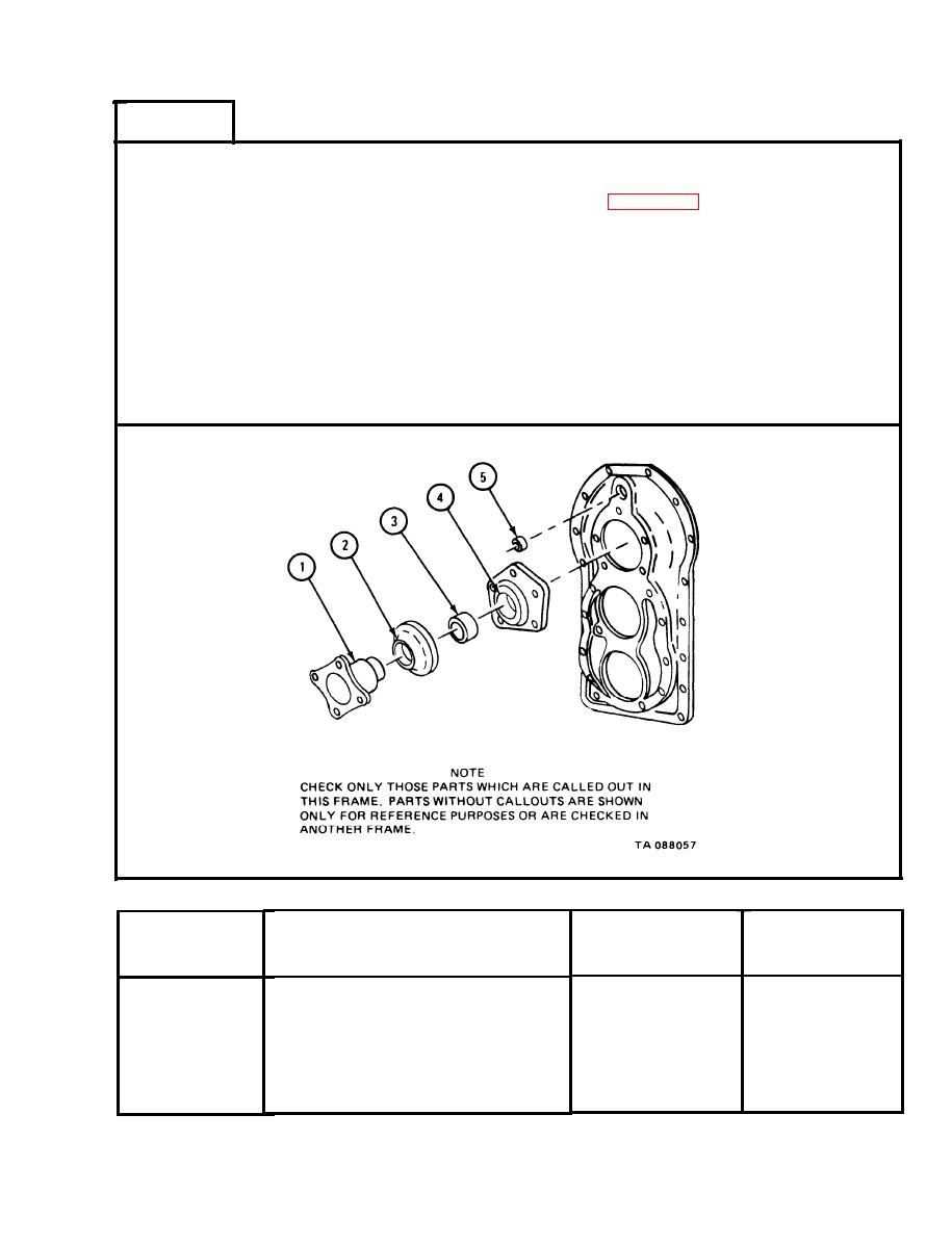
Table 2-35. Input Shaft Cover Wear Limits |
|
||
| ||||||||||
|
|
 TM 9-2520-246-34-1
FRAME 8
NOTE
Readings must be within limits given in table 2-35. If read-
ings are not within given limits, throw away part and get a
new one.
Measure flange outside diameter (1).
1.
Measure deflector inside diameter (2).
2.
Measure oil seal outside diameter (3).
3.
Measure input shaft cover bore (4).
4.
Measure oil seal outside diameter (5).
5.
GO TO FRAME 9
Input Shaft Cover Wear Limits
Table 2-35.
--
Size and Fit
Wear Limit
of New Parts
(inches)
(inches)
Item/Point of Measurement
Index Number
2.522 and 2.530
2.5150
1
Input shaft flange outside diameter
2.506 and 2.511
Deflector inside diameter
None
2
None
3.353 and 3.357
3
Oil seal outside diameter
3.3495
3.348 and 3.350
4
Input shaft cover bore
1.501 and 1.505
None
5
Oil seal outside diameter
2-195
|
|
Privacy Statement - Press Release - Copyright Information. - Contact Us |
