 |
|||
|
|
|||
|
Page Title:
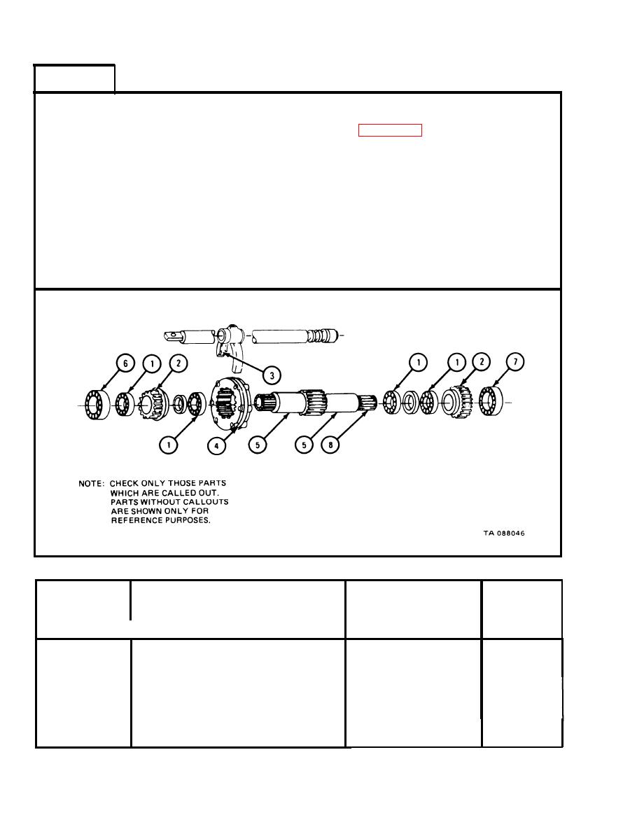
Table 2-24. Input Shaft Assembly Fits and Tolerances |
|
||
| ||||||||||
|
|
 TM 9-2520-246-34-1
FRAME 3
NOTE
Readings must be within limits given in table 2-24. The
letter L indicates a loose fit and the leter T indicates a
tight fit. If readings are not within given limits, throw
away part and get a new one.
1.
Measure fit of fork (3) on ring of clutch (4).
2.
Measure fit of four bearings (1) on input shaft bearing surface (5) in two places.
3.
Measure fit of front bearing (6) on input shaft bearing surface (5).
4.
Measure fit of rear bearing (7) on input shaft bearing surface (8).
5.
END OF TASK
Input Shaft Assembly Fits and Tolerances
Table 2-24.
Size and Fit
Wear Limit
of New Parts
(inches)
(inches)
Item/Point of Measurement
Index Number
0.0012L
0.0007T to 0.0009L
Fit of bearing in gear bore
1 and 2
0.0800L
0.0250L to 0.0380L
Fit of fork on clutch
3 and 4
O. 00 01T
0.0002T to 0.0007T
Fit of bearing on input shaft
1 and 5
0.000IT
0.0002T to 0.0007T
Fit of front bearing on input shaft
6 and 5
None
0.0009T to 0.0004T
Fit of rear bearing on input shaft
7 and 8
2-184
|
|
Privacy Statement - Press Release - Copyright Information. - Contact Us |
