 |
|||
|
|
|||
|
|
|||
| ||||||||||
|
|
 TM 9-2320-366-20-3
This task covers:
a. Removal
d. Installation
b. Disassembly
e. Follow-On Maintenance
c. Assembly
INITIAL SETUP
Equipment Conditions
Materials/Parts
Engine shut down (TM 9-2320-366-10-1).
Pin, Cotter (Item 224, Appendix G)
Cab raised (TM 9-2320-366-10-1).
Bushing, Sleeve (Item 6, Appendix G)
Tools and Special Tools
Tool Kit, Genl Mech (Item 46, Appendix C)
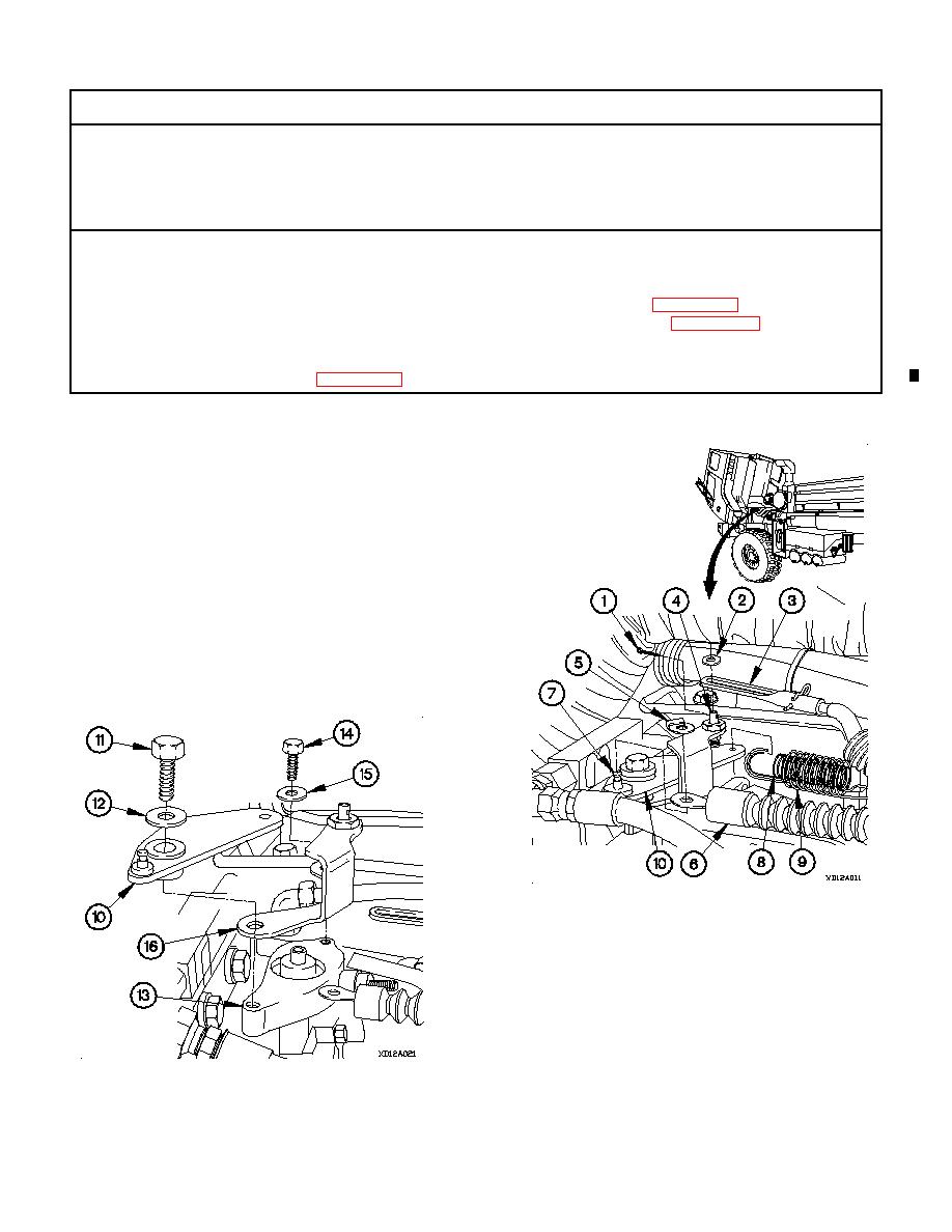
a. Removal.
(1) Remove cotter pin (1), washer (2), and TPS cable
assembly (3) from stud (4). Discard cotter pin.
(2) Remove clip (5) and throttle control cable (6) from stud
(7).
NOTE
Note position of two springs prior to removal.
(3) Remove springs (8 and 9) from linkage plate (10).
(4) Remove bolt (11), washer (12), and linkage plate (10)
from governor (13).
(5) Remove bolt (14), washer (15), and sensor bracket (16)
from governor (13).
Change 1
|
|
Privacy Statement - Press Release - Copyright Information. - Contact Us |
